2. BSB-LAN: The Software
In the following chapters the installation and the configuration of the BSB-LAN software is described. A description of the web interface, however, can be found in chap. 4, a description of the query and control options in chap. 5 and a description of the special functions in chap. 6.
2.1 Installation
The BSB-LAN software must be flashed to the used microcontroller (Arduino Due or ESP32) for installation. This can be done e.g. with the “Arduino IDE”, but of course other programs like “PlatformIO” or “Visual Studio Code” can be used as well.
| Note |
|---|
| In this manual it is assumed that the Arduino IDE is used. All descriptions and terms therefore refer to the Arduino IDE. If you are a beginner and not yet familiar with the Arduino IDE, you will find a description of how to install and configure the Arduino IDE in chap. 12. |
Depending on the used platform (Arduino Due or ESP32) the necessary settings of the Arduino IDE differ. Thus the appropriate board types must be installed and selected, the settings must be adapted platform-specifically etc. These settings will be mentioned in the following. It is assumed that the necessary libraries for the respective platform are already installed. If this is not the case, then you find information for this in chap. 12.
Beyond that there are still further things to consider with the installation on the ESP32, which are likewise treated in the appropriate chapter.
2.1.1 Installation onto the Due
The following describes the installation of the BSB-LAN software on an Arduino Due. The description refers to the use of the Arduino IDE. With the default settings of the BSB-LAN software DHCP is used for the IP address assignment. If you don’t want this and want to assign a fixed IP, please read chap. 2.2.2 and adapt the file BSB_LAN_config.h before flashing!
| Note |
|---|
| If you are using Windows, an additional driver installation may be necessary. See the page https://www.arduino.cc/en/Guide/ArduinoDue for further informations. |
It is advisable to proceed with the following steps:
-
Connect the Arduino setup with a USB cable to your computer. Use the ‘Programming Port’ of the Due, which is the USB port in the ‘middle’, placed next to the power supply socket. Both the LAN shield and the BSB-LAN adapter should already be plugged onto the Due beforehand, but this is not mandatory.
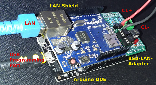
*The complete setup (Arduino Due + LAN-Shield + BSB-LPB-LAN-Adapter v3) including the corresponding cables.
-
Download the current BSB-LAN version and unzip the downloaded file BSB-LAN-master.zip.
-
Enter the folder “BSB-LAN-master”/”BSB_LAN” and rename the file BSB_LAN_custom_defs.h.default to BSB_LAN_custom_defs.h and BSB_LAN_config.h.default to BSB_LAN_config.h!
-
Open the BSB_LAN sketch by double clicking on the file BSB_LAN.ino in the BSB_LAN folder. The corresponding files BSB_LAN_config.h, BSB_LAN_custom_defs.h and BSB_LAN_defs.h are loaded automatically.
-
Select “Arduino Due (Programming Port)” under “Tools/Board”.
Note If the board is not listed, you have to add the Atmel SAM Core. Information about this can be found in chap. 12. -
Select the correct serial port where the Due is connected to the computer under “Tools/Port”.
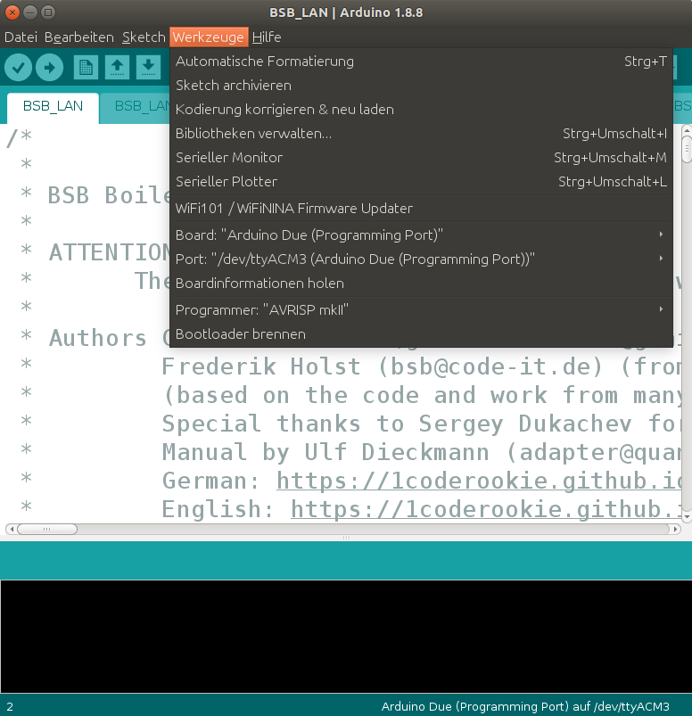
The settings for the Due in the Arduino IDE.
-
If you want to configure BSB-LAN by customizing the file BSB_LAN_config.h (see chap. 2.2.2), please do so now.
-
Start the flash process and upload the sketch to the Arduino Due by clicking on “Sketch/Upload”.
-
After finishing the flash process start the serial monitor of the Arduino IDE and watch the outputs which are generated when starting the Arduino Due. Among other things, the IP that is assigned to the setup when using DHCP will be diplayed there.
Congratulations - you have installed BSB-LAN!
Now proceed with configuring the BSB-LAN software and the connection and startup of the setup.
| Important Note |
|---|
In order to gain access to all of the parameters your controller offers, a controller specific file BSB_LAN_custom_defs.h must be created. Afterwards BSB-LAN must be reinstalled with this new file. Therefore please read the chap. 3.3 and perform the steps mentioned there! |
2.1.2 Installation onto the ESP32
In the following the installation of the BSB-LAN software on an ESP32 is described. The description refers to the use of the Arduino IDE. With the default settings of the BSB-LAN software DHCP is used for the IP address assignment. If you don’t want this and want to assign a fixed IP, please read chap. 2.2.2 and adapt the file BSB_LAN_config.h before flashing!
| Note |
|---|
| If the ESP32 board is not recognized by your operating system, you may need to install an additional driver for the USB chip used by the board. |
It is advisable to proceed with the following steps:
-
Connect your ESP32 board with a USB cable to your computer. You may have already plugged the BSB-LAN adapter on or under your ESP32 board, but this is not mandatory.
-
Download the current BSB-LAN version and unpack the downloaded file BSB-LAN-master.zip.
-
Enter the folder “BSB-LAN-master”/”BSB_LAN” and rename the files BSB_LAN_custom_defs.h.default to BSB_LAN_custom_defs.h and BSB_LAN_config.h.default to BSB_LAN_config.h!
-
Open the BSB_LAN sketch by double clicking on the file BSB_LAN.ino in the BSB_LAN folder. The corresponding files BSB_LAN_config.h, BSB_LAN_custom_defs.h and BSB_LAN_defs.h are loaded automatically.
-
Select the corresponding ESP32 board type under “Tools/Board”:
-
For the Joy-It ESP32-NodeMCU (or identical clones with an “ESP32-WROOM” chip) recommended in this manual the appropriate board type is “ESP32 Dev Module”.
-
For the recommended Olimex ESP32-EVB & ESP32-PoE please select the entry with the same name from the list.
Notes If the ESP32 framework is already installed and you see the different ESP32 board variants, please check in the “Board Manager” under “Tools/Boards” that version 2.0.2 (or higher, if available) is installed.
If the board is not listed, the ESP32 platform must be added in the Arduino IDE. Information about this can be found in Chapter 12.1.2. -
-
Select the correct serial port, where the ESP32 board is connected to the computer, under “Tools/Port”.
-
Set the transfer speed/baudrate to 115200 (Attention: In the Arduino IDE usually 921600 is preset for ESP32 boards!)
-
“Partition Scheme”: depending on the type of board, you need to choose the specific partition scheme.
-
For the recommended ESP32-NodeMCU please choose “Default 4MB with spiffs (1.2BM APP/1.5MB SPIFFS)”.
The following screenshot shows the configuration for the ESP32-NodeMCU.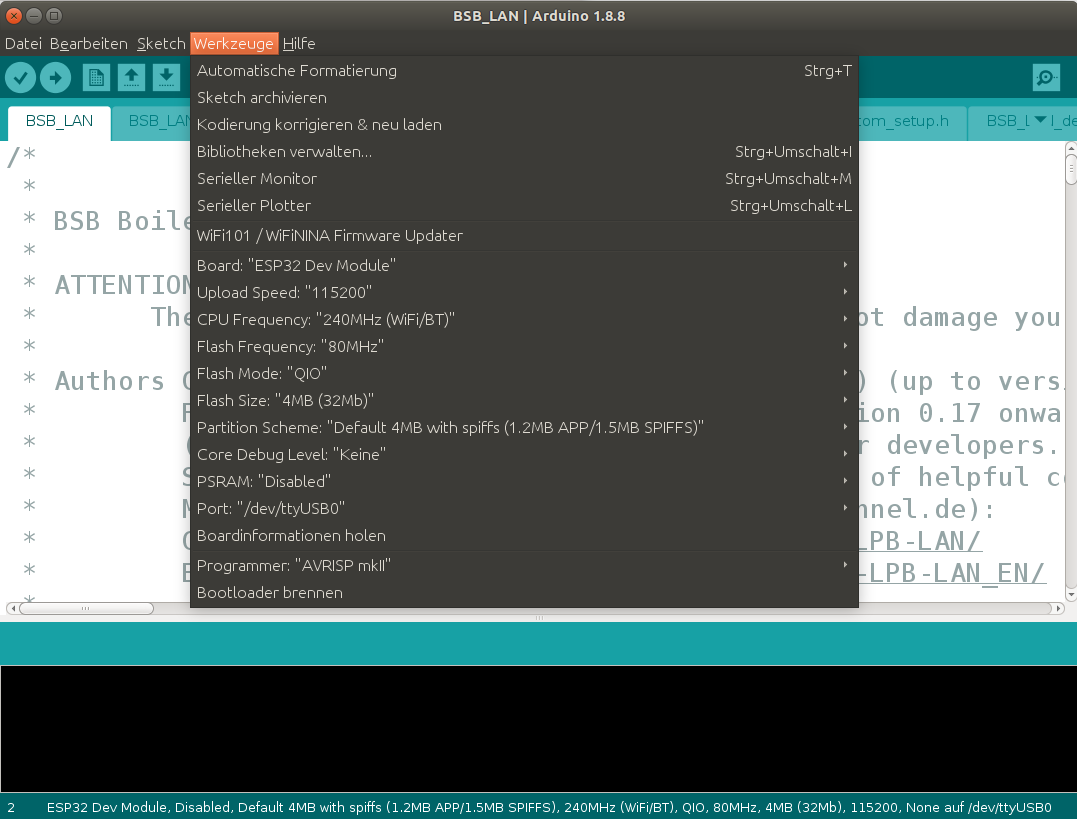
The settings for the ESP32 NodeMCU in the Arduino IDE.
-
For the recommended Olimex boards select the variant “Minimal SPIFFS (Large APPS with OTA)”.
-
-
Now click on the tab for the file BSB_LAN_config.h and adjust necessarily the following settings:
-
Activate the definition
#define WIFIin the file BSB_LAN_config.h if you want to use WiFi. If you are using an Olimex board and want to use LAN, please leave the definement deactivated://#define WIFI. -
If you want to use WiFi, enter the access data for your WiFi network at the entries
char wifi_ssid[32] = "YourWiFiNetwork";and
char wifi_pass[64] = "YourWiFiPassword";.
-
-
If you want to configure BSB-LAN by adapting the file BSB_LAN_config.h (see chap. 2.2.2), please do this now.
-
Start the flash process and upload the sketch to the Arduino Due by clicking on “Sketch/Upload”.
After finishing the flash process, start the serial monitor of the Arduino IDE and observe the outputs that occur when the ESP32 is started. Among other things, the IP that is assigned to the setup when using DHCP will be displayed there.
| Notes |
|---|
| If the ESP32 cannot connect to the configured WLAN, it will set up its own access point “BSB-LAN” with the password “BSB-LPB-PPS-LAN” for 30 minutes. After that, it will reboot and try again to connect to the configured WLAN network. |
| Although the logging feature also works with the ESP32, it is not recommended to overuse this feature due to wear and tear of the flash memory. If the Olimex board is to be used, a microSD card can be used instead of the SPIFF flash memory. The usage has to be activated in the file BSB_LAN_config.h. |
Congratulations - you have installed BSB-LAN!
Now proceed with configuring the BSB-LAN software and the connection and startup of the setup.
| Important Note |
|---|
In order to gain access to all of the parameters your controller offers, a controller specific file BSB_LAN_custom_defs.h must be created. Afterwards BSB-LAN must be reinstalled with this new file. Therefore please read the chap. 3.3 and perform the steps mentioned there! |
2.1.3 Updates
Updating the BSB-LAN software is done by the usual flashing of the new version (download as ZIP file, via git or similar), as described in the previous installation chapters. Please pay attention to the following notes!
For ESP32 based boards (Olimex, NodeMCU) an OTA update (“OverTheAir” update) can be done alternatively (this function is NOT usable with the Arduino DUE!). For this, the corresponding OTA function must be activated in the web config or the file BSB_LAN_config.h. The belonging firmware file BSB_LAN_ino.bin can be created in the Arduino IDE under “Sketch / Export compiled binary file…”. The file has to be uploaded via browser to port 8080 of the BSB-LAN IP (http://<BSB-LAN-IP>:8080 or http://bsb-lan:8080 with activated MDNS).
| Notes |
|---|
| When updating to v3.x please do not use any existing files - please install BSB-LAN completely new! Also note the necessary creation of a controller specific BSB_LAN_custom_defs.h - the procedure is described in chap. 3.3. |
| If you have made certain changes in the file BSB_LAN_config.h for the new version to be flashed, e.g. the access data for your WLAN or a fixed IP, which were apparently not accepted after flashing, this is usually due to the fact that the old settings were read from the EEPROM. To make the new settings effective, set the setting “Read configuration from EEPROM” in the Web configuration once to “Off”, save the change and flash again. After that the new settings should have become effective, because BSB-LAN has now read them from the file BSB_LAN_config.h and not from the EEPROM. After successful check set “Read configuration from EEPROM” again to “On”. |
| The existing and (if necessary) adapted file BSB_LAN_config.h can usually be taken over when updating to a newer version, but it is advisable to use the current file BSB_LAN_config.h.default instead of the existing file BSB_LAN_config.h. To do this, the file BSB_LAN_config.h.default must be renamed as before and, if necessary, adapted to the previous settings. This way you can be sure that you have made a complete update of the BSB-LAN software. |
| If the adapter is connected to the bus of the heating controller, it can remain connected if the Due/ESP32 is to be flashed again. There is no need to disconnect the adapter from the controller when updating BSB-LAN. |
| If you enable the function “check for updates” within the config, newer versions of BSB-LAN will be mentioned at the start page of the webinterface. This includes development versions also though (and not only ‘stable’ releases) - so if you only want to use a ‘stable’ release, you have to check for that manually at the project page. |
2.2 Configuration
The BSB-LAN software can be configured according to individual requirements. The configuration can be done in two ways: by adapting the BSB_LAN_config.h file and via the web interface. The configuration options are explained in more detail below. The descriptions in chapter 2.2.2 are generally more detailed, so it makes sense to study both chapters in detail.
2.2.1 Configuration via Webinterface
The settings overview or the web configuration interface is in principle self-explanatory, nevertheless the individual points are listed here again with a short explanation.
For a more detailed explanation of the individual functions, please refer to chap. 2.2.2.
The overview of the web configuration is divided into three columns:
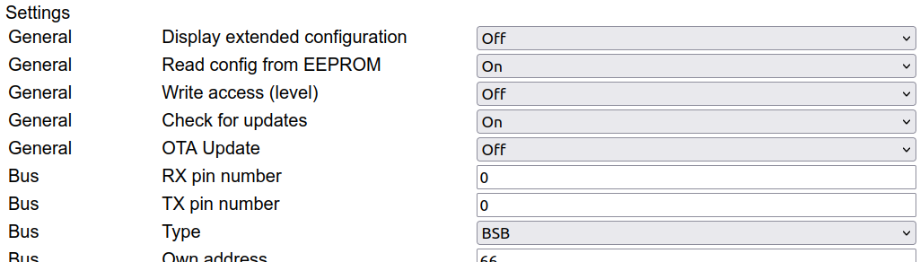
- For the sake of clarity, a rough category is displayed in the left column (e.g. “General”, “Bus”, etc.), so that the assignment of the respective entry is already apparent at first glance.
- In the middle column the function is named.
- In the right column is the corresponding field, which shows the current entry or setting. The entries from the file BSB_LAN_config.h are taken over, that means that also with deactivated functions the default settings are visible, so that it becomes clear, how (e.g.) parameters should be entered. Depending on the type of setting either a pull down menu with the available settings or only a field is displayed.
| Important |
|---|
| To apply changed settings, you must finally click on the button “Save parameter” at the bottom! |
In the following, the tabular overview of the functions with the (default) settings and the corresponding explanations (unfortunately, the naming of the left column “Category” must be omitted here for reasons of space and presentation):
| Function | (default) Setting | Explanation |
|---|---|---|
| Display extended configuration | Off | Displays the advanced settings of BSB-LAN (Off/On). For accessing all setting options of BSB-LAN “On” must be selected (and then click on “Save parameters” below). |
| Read config from EEPROM | On | Reads the stored configuration from the EEPROM when starting the Due (Off/On). These settings can deviate from the default settings, which were made in the file BSB_lan_config.h. If the settings stored in the EEPROM should be overwritten, e.g. during an update, set to “Off” and save the setting before flashing! If the setting is “Off”, changes will only remain active until the Due is restarted. |
| Write access (level) | Off | Write access of the adapter to the heating controller (Off/Standard/Complete). If write access to the heating controller should be granted, it is recommended to select the ‘Standard’ setting, in which case almost all available parameters can be written. In contrast to ‘Complete’, however, some function-critical parameters cannot be changed, as they are protected again inside the controller. The setting ‘Complete’ should therefore only be selected in exceptional cases and with caution and a very good knowledge of the controller functionality! |
| Check for updates | Off | Automatically check for updates of BSB-LAN (Off/On) |
| OTA Update | Off | OTA update function (OTA = Over The Air) deactivated (Off) / activated (On). For the further procedure for OTA updates please read chap. 2.1.3 Updates. |
| RX pin number | 0 | 0 = autoselect. If another pin than the preset RX pin (see file BSB_LAN_config.h) is used, it must be entered here. |
| TX pin number | 0 | 0 = autoselect. If another pin than the preset TX pin (see file BSB_LAN_config.h) is used, it must be entered here. |
| Type | BSB | Used bustype (BSB/LPB/PPS) |
| Own address | 66 | Own address of the adapter |
| Destination address | 0 | Destination address for queries |
| PPS: PPS mode | passive | PPS only: Users who use the adapter on the PPS interface must make two settings: First, the mode in which the bus is to be accessed (passive/as room unit) must be selected. When using a QAA room device, “passive” must be selected here. Then only the values that go via the bus are displayed in the web interface, writing of values is then not possible. If “as room unit” is selected here, values can also be sent to the heating system via the web interface. The type of the room device to be emulated must then still be selected (see below). There should then be no other room device on the bus, otherwise both transmitters send their own values to the heater, so that no consistent operation is possible. |
| PPS: QAA model | QAA70 | PPS only: Type of the room unit that should be imitated (QAA50/QAA70). |
| Device family | 0 | 0 = automatic controller recognition active (recommended setting). In case of a faulty detection, the device family (output of /6225) of the connected controller can be set here. |
| Device variant | 0 | 0 = automatic controller recognition active (recommended setting). In case of a faulty detection, the device variant (output of /6226) of the connected controller can be set here. |
| URL Passkey | -no default setting- | Optional security function: “URL Passkey” |
| HTTP authentification | -no default setting- | Optional security function: “User-Pass” (Basic HTTP Auth). Syntax: Username:Password |
| DHCP usage | On | DHCP usage (= automatic allocation of the IP address by the router) (Off/On) |
| IP address (fixed) | 192.168.178.88 | Manual network configuration: fixed IP address |
| Subnet | 255.255.255.0 | Manual network configuration: Subnet |
| Gateway | 192.168.178.1 | Manual network configuration: IP address of the gateway |
| DNS Server | 192.168.178.1 | Manual network configuration: IP address of the DNS server |
| TCP Port | 80 | TCP port of the setup |
| MAC address | 00:80:41:19:69:90 | (Preset) MAC address of the LAN shield or MAC address of the ESP |
| Trusted IP address | 0.0.0.0 | Optional security function: “Trusted IP”, access is only possible from this IP |
| Trusted IP address | 0.0.0.0 | Optional security function: “Trusted IP”, access is only possible from this IP |
| WLAN SSID | -no default setting- | SSID of the WLAN when using the WiFi-ESP-solution |
| WLAN password | -no default setting- | Password of the WLAN when using the WiFi-ESP-solution |
| mDNS Hostname | BSB-LAN | Hostname |
| Logging mode | -no default setting- | Different options for the logging mode (multiple options possible): Write to SD card / Calculate 24h averages / Send to MQTT broker / Send to UDP |
| Interval (seconds) | 3600 | Loginterval in seconds |
| Parameters | 8700,8743,8314 | Parameters to be logged |
| Bus telegrams | Off | Logging of bus telegrams activated (Off/-various options-), the desired setting is to be made according to the respective option description. |
| Parameter | 8700,8326 | Parameters for the 24h average calculation |
| Usage | Plain Text | Plain Text / JSON / Rich JSON |
| IP address broker | 192.168.178.20 | IP-Adresse des MQTT-Brokers |
| Username | User | MQTT: Username when using username/password |
| Password | Pass | MQTT: Passwort when using username/password |
| Device ID | BSB-LAN | Device name (header in JSON payload) |
| Topic prefix | BSB-LAN | Topic prefix of the MQTT messages |
| Pins | 0 | Used pin(s) for OneWire sensors (DS18B20) (0 = deactivated) |
| Pins | 0 | Used pin(s) for DHT22 sensors (0 = deactivated) |
| Sensoren | 0 | Amount of connected BME280 sensors |
| DHW push button: pin | 0 | Room unit emulation: used pin for the DHW push |
| RU1 temperature sensor parameter | -no default setting- | Room unit 1 emulation: enter the specific parameter number(s) for the optional room temperature sensor(s) here. Up to five sensors are possible, parameter numbers must be separated only with a comma. If more than one sensor is used, an automatic average will be calculated. |
| RU1 presence button: pin | 0 | Room unit 1 emulation: used pin for the presence button for HC1 |
| RU2 temperature sensor parameter | -no default setting- | Room unit 2 emulation: enter the specific parameter number(s) for the optional room temperature sensor(s) here. Up to five sensors are possible, parameter numbers must be separated only with a comma. If more than one sensor is used, an automatic average will be calculated. |
| RU2 presence button: pin | 0 | Room unit 2 emulation: used pin for the presence button for HC2 |
| RU3 temperature sensor parameter | -no default setting- | Room unit 3 emulation: enter the specific parameter number(s) for the optional room temperature sensor(s) here. Up to five sensors are possible, parameter numbers must be separated only with a comma. If more than one sensor is used, an automatic average will be calculated. |
| RU3 presence button: pin | 0 | Room unit 3 emulation: used pin for the presence button for HC3 |
| Usage | Off | Use MAX! devices (Off/On) |
| IP address cube | 192.168.178.5 | IP address of the CUNO/CUNX/modified MAX!Cube |
| Devices | KEQ0502326,KEQ0505080 | Serial numbers of the MAX! devices to be used |
| Usage | Off | Use IPWE extension (URL/ipwe.cgi) (Off/On) |
| Parameters | 8700,8743,8314 | Parameters that should be displayed within the IPWE extension |
| Usage | Serial | Use debug function (Off/Serial/Telnet) |
| Verbosity mode | On | Verbosity mode activated (Off/On) |
| Monitor mode | Off | Monitor mode activated (Off/On) |
| Display unknown parameters | On | Displays unknown / not supportet parameters (“error 7 - parameter not supportet”)-(On/Off). |
2.2.2 Configuration by Adjusting the Settings Within BSB_LAN_config.h
The BSB-LAN software can be configured by adjusting the settings in the file BSB_LAN_config.h. All settings are listed below in the same way as they are listed and preset in the file. It is therefore advisable to work through the settings point by point with this manual at hand.
| Note |
|---|
| To ‘activate’ or a definement you have to delete the two slashes in front of the hashtag, to ‘deactivate’ a definement you have to add two slashes in front of the hashtag. E.g.: A deactivated definement: //#define XYZ An activated definement: #define XYZ |
- The language of the user interface of the web interface of the adapter as well as the category and parameter designations must be selected or defined. For “English” the following definition must be selected:
#define LANG EN
Starting with BSB-LAN v.042 it is possible to use BSB-LAN in other languages, too, whereby in principle any language can be supported (only’ the corresponding translations have to be created).
Currently available are: Czech (CZ), German (DE), Danish (DK), English (EN), Spanish (ES), Finnish (FI), French (FR), Greek (GR), Hungarian (HU), Italian (IT), Dutch (NL), Polish (PL), Russian (RU), Swedish (SE), Slovenian (SI) and Turkish (TR). If certain expressions are not available in the specific language, the English expression is automatically displayed. If this is also not available, the German expression is finally displayed.
-
Load configuration settings from EEPROM or from the file BSB_LAN_config.h:
byte UseEEPROM = 1;According to the default setting, the configuration settings are read from the EEPROM when BSB-LAN is started. As a fallback the variable can be set to ‘0’, then the settings are read from the file BSB_LAN_config.h.
Network settings:
| Note |
|---|
| By default, the usage of DHCP is activated, so you don’t have to change any network settings. If you want to use a fixed IP though, deactivate DHCP and set the IP and the addresses of the Gateway and the Subnet accordingly. |
-
MAC address of the ethernet shield:
byte mac[] = { 0x00, 0x80, 0x41, 0x19, 0x69, 0x90 };The default MAC address can be kept. A change is usually only necessary if more than one adapter is used (in any case, you should make sure that each MAC address only occurs once in the network!). In this case, changes should only be made to the last byte (e.g. 0x91, if a second adapter is used).
Note The MAC address which can be set here doesn’t apply to the WiFi-ESP-solution! There the MAC address can’t be set! The MAC address assigned here also influences the host name (or is a part of it), which is assigned by the router when using DHCP (see below): The host name consists of the identifier “WIZnet” and the last three bytes of the MAC address. For the default MAC address mentioned above, the host name is thus “WIZnet196990”. This host name is usually also displayed as such in the router. In this case the web interface of BSB-LAN can be reached in the browser under http://wiznet196990.
If a second adapter is used and the MAC address will be changed to (e.g.)
byte mac[] = { 0x00, 0x80, 0x41, 0x19, 0x69, 0x91 };
the host name is “WIZnet196991” orhttp://wiznet196991. -
Ethernet port:
uint16_t HTTPPort = 80;Port 80 for HTTP is preset.
-
DHCP:
bool useDHCP = true;By default DHCP is used. If this is not desired and you want to assign a fixed IP address by yourself, set the variable to false.
Note Please see the notes above regarding the hostname based on the MAC address. The IP given by the router will also appear within the start process of the Arduino Due within the serial monitor of the Arduino IDE. -
IP address:
byte ip_addr[4] = {192,168,178,88};Fixed IP address of the adapter, if DHCP is not used - please note the commas instead of dots!
Note If you want to give the adapter a fixed IP, please make sure that it occurs only once in your network! -
Gateway address:
byte gateway_addr[4] = {192,168,178,1};IP address of the gateway (usually the one of the router itself) - please note the commas instead of dots!
-
Subnet:
byte subnet_addr[4] = {255,255,255,0};Address of the subnet - please note the commas instead of dots!
-
WiFi:
//#define WIFIThis definement has to be activated if the WiFi function of the ESP8266-WiFi-solution or the ESP32 should be used.
char wifi_ssid[32] = "YourWiFiNetwork";For the usage of WiFi, YourWiFiNetwork has to be replaced by the SSID of the WiFi network.
char wifi_pass[64] = "YourWiFiPassword";For the usage of WiFi, YourWiFiPassword has to be replaced by the password of the WiFi network.
#define WIFI_SPI_SS_PIN 12The SS pin to be used at the DUE when using the ESP8266-WiFi-solution is defined here. It is advisable to leave the default setting. If, however, another pin should be used, it is essential to ensure that the desired pin is neither used elsewhere nor is included in the list of protected pins.
Note The MAC address can’t be set within the WiFi-ESP-solution!
-
Using Multicast DNS:
#define MDNS_SUPPORTchar mDNS_hostname[32] = "BSB-LAN";By default the usage of Multicast DNS with the hostname “BSB-LAN” is activated, so that you can find the adaptersetup under this name within your network.
Note mDNS is only available when using LAN, it is not available if you are using the WiFi solution using an ESP8266!
-
Aquiring time and date via NTP server:
#define USE_NTP // Disable this in case you don't want to use NTP
const char ntp_server[20] = "pool.ntp.org";
const char local_timezone[30] = "CET-1CEST,M3.5.0,M10.5.0/3";By default this function is activated.
Note Aquiring time and date via NTP server only works with ESP32 boards! * NTP settings to acquire exact date and time via network. * Attention: This only works with ESP32 microcontrollers so far! * Use pool.ntp.org if your BSB-LAN installation can access the internet. * Otherwise you may also use your router's address if it can act as a NTP server. * The default timezone "CET-1CEST,M3.5.0,M10.5.0/3" covers most Central European countries (GMT+1) and takes care of daylight saving. * Use "EET-2EEST,M3.5.0/3,M10.5.0/4" for Eastern European countries (GMT+2), or * use "WET0WEST,M3.5.0/1,M10.5.0" for Western European countries (GMT+0). * See here for a full list of timezones for places all over the world: * https://github.com/nayarsystems/posix_tz_db/blob/master/zones.csv
-
Debugging and related settings:
-
#define DEBUGThe debug module will be compiled (activated by default).
-
byte debug_mode = 1;The following debug options are available:
0 - debugging deactivated
1 - send debug messages to the serial interface (e.g. for using the aerial monitor of the Arduino IDE); default setting
2 - send debug messages to a TelNet client instead of the serial interface
-
byte verbose = 1;By default the verbose mode is activated (= 1), so that (besides the raw data) the respective plaintext (if available) of parameters and values is displayed. It is advisable to leave this setting as it facilitates possible trouble shooting. Furthermore, this setting is necessary if telegrams and command IDs of new parameters should be decoded.
-
byte monitor = 0;Bus monitor mode, deactivated by default; set to ‘1’ to activate
-
bool show_unknown = true;All parameters including the unknown parameters (error message “error 7 (parameter not supported)”) are displayed when querying via web interface (e.g. when querying a complete category); default setting.
If you want to hide the ‘unknown’ parameters that are not supported by the controller of your heating system (e.g. when querying a complete category), you have to set the variable to ‘false’ (bool show_unknown = false;). The parameters are still queried in such a query (e.g. for a complete category) though.
-
Security functions:
There are several options to control and protect access to your heating system. However, keep in mind, that even activating all three options are no guarantee that a versatile intruder with access to your (W)LAN won’t be able to gain access. In any case, no encryption of data streams is provided by the Arduino itself. Use VPN or a SSL proxy if that is a must for you and connect the Arduino wired to the VPN server or SSL proxy.
The following three security options are available within BSB-LAN:
-
Passkey:
To protect the system from unwanted access from outside, the function of the security key (PASSKEY) can be used (very easy and not really secure!):
char PASSKEY[64] = "";To use this function, add a certain sequence of alphanumerical characters as a simple security function, e.g.
char PASSKEY[64] = "1234";→ in this example the passkey is ‘1234’. If no alphanumerical sequence is set (default), the passkey function remains deactivated.Note If PASSKEY is defined, the URL has to contain the defined passkey as first element, e.g.: URL/1234/to view the main website!
Only within the URL of the optional IPWE extension the passkey has NOT to be added!Don’t forget the trailing slash!. -
Trusted IP:
byte trusted_ip_addr[4] = {0,0,0,0};
byte trusted_ip_addr2[4] = {0,0,0,0};Within these variables you can define up to two IP addresses from which the access to BSB-LAN will then be possible (e.g. sever of your home automation system).
If the default setting will not be changed or if the first number is a ‘0’, this function is deactivated (default setting). -
User-Pass:
char USER_PASS[64] = "";Provides a username:password based access (default setting: deactivated). No encryption! Syntax is Username:Password as shown in the deactivated example:
//char USER_PASS[64] = "User:Password";
Settings for optional sensors:
-
OneWire temperature sensors (DS18B20):
#define ONE_WIRE_BUS
byte One_Wire_Pin = 0;If you want to use OneWire temperature sensors (DS18B20), the definition must be activated and the corresponding GPIO-pin number must be defined.
By default, the module is activated and pin 0 is set (0 = OneWire usage deactivated). -
DHT22 sensors:
#define DHT_BUS
uint8_t DHT_Pins[10] = {0};If you want to use DHT22 sensors (temperature & humidity; max. amount: 10), the definement must be activated and the corresponding pin(s) must be be defined.
By default, the module is activated and pin 0 is set (0 = DHT usage deactivated).
-
BME280 sensors:
#define BME280byte BME_Sensors = 0;If you want to use BME280 sensors (temperature, humidity & barometric pressure), the definement must be activated and the corresponding amount of sensors (default 0 = deactivated, maximum 2) must be be defined. The sensors have to be connected to the I2C bus. The address of the first sensor mus be 0x76, the one of the second sensor 0x77.
-
24h averages:
#define AVERAGESIf you want to create 24h averages from certain parameters, the definement must be activated (default setting).
Further more you have to list the specific numbers of the parameters (up to 40) you want to be calculated. E.g.:
parameter avg_parameters[40] = {
  {8700, -1},                         // Außentemperatur
  {8326, -1}                          // Brenner-Modulation
};
If an SD card is available, the current values are saved there regularly in order to be able to continue the calculation without gaps after a restart.
If the average values of the parameters set above are also to be written to a log file and displayed via URL command
/DGor sent via MQTT, for example, they must be listed as special parameters with the numbers 20050-20099 in the parameters to be logged (see below)! The corresponding logging settings (see below), such as the log interval, then apply to them.
-
Logging (also to microSD card) and/or usage of MQTT/UDP:
#define LOGGER→ The logging module will be compiled.Attention The activated definement is a requirement for logging to a microSD card as well as for using MQTT and UDP! In the following, various settings can/should be made:
-
Sending logdata via UDP broadcast:
#define UDP_LOG_PORT 6502→ Logdata will additionally be send as a UDP broadcast message to port 6502 (default). You can set the desired UDP port here. -
If you are using a microSD card adapter on an ESP32-based board and want to log data to the card (recommended!) instead of the SPIFFs flash storage, activate the following definement:
//#define ESP32_USE_SD -
If ‘raw’ bus telegrams should be logged, the selection can be specified. The telegrams are stored within the file journal.txt on the microSD card. By default the logging of these bus messages is deactivated:
int logTelegram = LOGTELEGRAM_OFF;The following options are available:
LOGTELEGRAM_OFF→ no logging of bus telegrams (default setting)LOGTELEGRAM_ON→ all bus telegrams are loggedLOGTELEGRAM_ON + LOGTELEGRAM_UNKNOWN_ONLY→ only unknown bus telegrams are loggedLOGTELEGRAM_ON + LOGTELEGRAM_BROADCAST_ONLY→ only broadcast telegrams are loggedLOGTELEGRAM_ON + LOGTELEGRAM_UNKNOWNBROADCAST_ONLY→ only unknown broadcast telegrams are logged -
bool logCurrentValues = false;The data of the parameters to be logged are stored in the file ‘datalog.txt’ on the microSD card (deactivated by default). For activating this function the variable must be set to ‘true’.
-
unsigned long log_interval = 3600;The desired logging interval in seconds.
Attention This interval must also be set for using MQTT, even though if no data should be logged! The parameters that should be logged must be listed as follows (destination address -1 means the default destination address):
parameter log_parameters[40] = {
  {8700, -1},                   // Außentemperatur
  {8743, -1},                  // Vorlauftemperatur
  {8314, -1},                  // Rücklauftemperatur
-
-
MQTT:
Note The parameters that should be queried and the interval for sending the values must be defined within the logger definement as mentioned above. If you want to use MQTT the belonging variables and settings besides the above mentioned settings have to be adjusted:
-
define MQTT→ The MQTT module will be compiled (default setting). -
byte mqtt_mode = 0;→ MQTT is deactivated (default setting); the following options are available:1 = send messages in plain text format
2 = send messages in JSON format. Use this if you want a json package of your logging information printed to the mqtt topic
Structure of the JSON payload:
{"MQTTDeviceID": {"status":{"log_param1":"value1","log_param2":"value2"}, ...}}3 = send messages in rich JSON format. Use this if you want a json package of your logging information printed to the mqtt topic
Structure of the rich JSON payload:
{"MQTTDeviceID": {"id": one_of_logvalues, "name": "program_name_from_logvalues", "value": "query_result", "desc": "enum value description", "unit": "unit of measurement", "error", error_code}} -
byte mqtt_broker_ip_addr[4] = {192,168,1,20};→ IP of the MQTT broker (standard port 1883). Please note the commas insted of dots! -
char MQTTUsername[32] = "User";→ Set username for MQTT broker here or set zero-length string if no username/password is used. -
char MQTTPassword[32] = "Pass";→ Set password for MQTT broker here or set zero-length string if no password is used. -
char MQTTTopicPrefix[32] = "BSB-LAN";→ Optional: Choose the “topic” for MQTT messages here. If zero-length string here, default topic name used. -
char MQTTDeviceID[32] = "MyHeater";→ Optional: Define a device name to use as header in json payload. If zero-length string here, “BSB-LAN” will be used.
-
-
IPWE:
#define IPWE→ The ipwe module will be compiled.
bool enable_ipwe = false;By default, the usage of the ipwe extension (URL/ipwe.cgi) is deactivated. If you want to use it, set the variable to ‘true’.
Define the parameters that should be displayed (max 40):parameter ipwe_parameters[40] = { {8700, -1}, // Außentemperatur {8743, -1}, // Vorlauftemperatur {8314, -1}, // Rücklauftemperatur };
-
MAX! (CUNO/CUNX/modified MAX!Cube):
If you want to use MAX! thermostats, adjust the following settings:
-
//#define MAX_CUL→ activate the definement (deactivated by default) -
bool enable_max_cul = false;→ set the variable to ‘true’ (default value: ‘false’) -
byte max_cul_ip_addr[4] = {192,168,178,5};→ Set the IP address of the CUNO/CUNX/modified MAX!Cube - please note the commas instead of dots! -
Define the MAX! thermostats that should be queried (max 20) by entering the 10 digit serial number / MAX! ID:
 char max_device_list[20][11] = {
 "KEQ0502326",
 "KEQ0505080"
 };
See chapter 7.3 for further informations about MAX! components.
-
-
Define the number of retries for the query command (default value is 3, doesn’t need to be changed usually):
#define QUERY_RETRIES 3
Settings of the bus pins and bus type:
-
RX/TX pinconfiguration:
byte bus_pins[2] = {0,0};→ automatic detection and selection of the used pins (RX,TX)Possible options:
- Hardware serial (since adapter v3) Arduino Due: RX = 19, TX = 18 (
{19,18}); NodeMCU: 16,17; Olimex EVB 36,17. - Software serial (up to adapter v2 & Arduino Mega 2560): RX = 68, TX = 69 (
{68,69})
- Hardware serial (since adapter v3) Arduino Due: RX = 19, TX = 18 (
-
Bus type / protocol:
uint8_t bus_type = 0;→ Depending on the connection of the adapter to the controller of your heating system (BSB/LPB/PPS), the corresponding bus type must be set (default value is 0 = BSB).Possible options:
- 0 = BSB
- 1 = LPB
- 2 = PPS
-
Bus settings:
Depending on the bus type, you can/must adjust certain settings:
-
BSB:
byte own_address = 0x42;→ sets own address of the BSB-LAN adapter; default setting is ‘0x42’ = 66, which is ‘LAN’ in serial monitorbyte dest_address = 0x00;→ destination address of the heating system; preset: 0See chap. 2.1.1 for further informations.
-
LPB:
byte own_address = 0x42;→ own address of the BSB-LAN adapter; preset: segment 4, device 3byte dest_address = 0x00;→ destination address of the heating system; preset: segment 0, device 1See chap. 2.1.2 for further informations.
-
PPS:
bool pps_write = 0;→ readonly access (default setting)If you want to enable writing to the controller of the heating system, set the variable to ‘1’.
Note Only enable writing if there is no other ‘real’ room unit such as QAA50/QAA70! byte QAA_TYPE = 0x53;→ type of the room unit which should be imitated:
0x53 = QAA70 (default setting) 0x52 = QAA50
0x37 = QAA95
0x66 = BMU
0xEA = MCBA/DC225 -
-
Detection or fixed setting of the controller type of the heating system:
static const int fixed_device_family = 0;
static const int fixed_device_variant = 0;By default, the automatic detection of the controller type is active. Usually there is no need to change this setting. However, you can set the type manually though, but you should only change this if you really know what you are doing! In that case set the variables of
fixed_device_familyandfixed_device_variantto your device family and variant (parameters 6225 and 6226).
-
Read/write access to the controller:
#define DEFAULT_FLAG FL_SW_CTL_RONLYBy default, only read-access to the controller of the heating system is granted for the BSB-LAN adapter. If you want to make all parameters writeable / settable, then you can adjust this setting within the webinterface of BSB-LAN (menu “settings”).
Note for Mega-user The possibility to configure BSB-LAN via the webinterface doesn’t exist within the usage of the Mega 2560, because the module WEBCONFIG can’t be compiled and used due to the limited memory of the Mega. In this case you still have to grant write access by setting the flag ‘0’: #define DEFAULT_FLAG 0
-
Include own code:
//#define CUSTOM_COMMANDSThis includes commands from the file BSB_lan_custom.h to be executed at the end of each main loop (deactivated by default).
-
Check for Updates of BSB-LAN:
#define VERSION_CHECK
bool enable_version_check = false;Check for new versions when accessing BSB-LAN’s main page (internet access needed). Doing so will poll the most recent version number from the BSB-LAN server. This function is deactivated by default; to activate this function, set the variable to ‘true’.
Note In this process, it is unavoidable that your IP address will be transferred to the server, obviously. We nevertheless mention this here because this constitutes as ‘personal data’ and this feature is therefore disabled by default. Activating this feature means you are consenting to transmitting your IP address to the BSB-LAN server where it will be stored for up to two weeks in the server’s log files to allow for technical as well as abuse analaysis. No other data (such as anything related to your heating system) is transmitted in this process, as you can see in the source code.
-
OTA update (only ESP32):
#define ENABLE_ESP32_OTA
boolean enable_ota_update = false;OTA update (OTA = OverTheAir) for ESP32 based boards (default: deactivated). To enable this function
boolean enable_ota_update = true;must be set. The belonging firmware file can be created in the Arduino IDE under “Sketch / Export compiled binary…”. The file has to be uploaded to port 8080 of the BSB-LAN IP.
-
“External” webserver:
//#define WEBSERVERUsage of the “external” web server if definement is active. Please see chapter6.9 for further informations.
-
Store configuration in EEPROM:
#define CONFIG_IN_EEPROMStores the configuration in the EEPROM. If you don’t want to use this function, deactivate the definement.
-
Compile web-based configuration and EEPROM config store module extension:
#define WEBCONFIGActivates the configuration via webinterface.
-
Compile JSON-based configuration and EEPROM config store module extension.
#define JSONCONFIG
-
Variables for future use, no function yet:
#define ROOM_UNIT→ compile room unit replacement extension
byte UdpIP[4] = {0,0,0,0};→ destination IP address for sending UDP packets to
uint16_t UdpDelay = 15;→ interval in seconds to send UDP packets#define OFF_SITE_LOGGER→ compile off-site logger extension
byte destinationServer[128] = "";→ URL string to periodically send values to an off-site logger
uint16_t destinationPort = 80;→ port number for abovementioned server
uint32_t destinationDelay = 84600;→ interval in seconds to send values
2.3 Adding Parameters Manually From v2.2
Compared to previous versions of BSB-LAN, you may notice that some parameters now no longer appear in the device-specific parameter list, even if they seemed to work fine in previous versions.
However, it is still possible to include selected parameters from the parameter list of version 2.2 in the current version.
| Note |
|---|
| We strongly recommend to add these parameters, which are not officially supported by the controller manufacturer, only after a thorough check, especially if these values should also be written! |
| As a safe number range in which parameters can be added as described below, we recommend 10600 and warm up. |
The first step is to download the Release version 2.2 at https://github.com/fredlcore/BSB-LAN/releases.
After unpacking the file, you will find the file BSB_LAN_custom_defs.h.default in the subdirectory BSB_LAN. Open this file with a text editor like Notepad under Windows or TextEdit under MacOS.
In parallel you also open the file BSB_LAN_custom_defs.h from the current BSB-LAN version you want to use in the Arduino IDE.
When both files are open, look for the parameter number of the parameter you want to add in the BSB_LAN_custom_defs.h.default of version 2.2.
The further steps are explained using the example of the former parameter 701 “Presence button (temporary absence)”. This parameter is now included by default in the device-specific BSB_LAN_custom_defs.h file; it is only missing in the first files created (during the conversion phase to BSB LAN version 3.x at that time).
Searching for “701” first results in this entry:
const char STR701[] PROGMEM = STR701_TEXT;
Copy this line to the clipboard.
In the file BSB_LAN_custom.defs.h of the current BSB-LAN version you now search for the text const char S and find a number of such entries. There you insert the above selected line at any position.
If no entry starting with const char is found for a parameter, but an entry corresponding to the pattern #define STR<searched parameter number> STR<referenced parameter number>, two steps are necessary:
First you copy the line #define STR... into the current BSB_LAN_custom_defs.h file and then you search in the BSB_LAN_custom_defs.h.default for the referenced parameter number until you find the line for this number that starts with const char S.
Using the parameter number 702 as an example, this line would therefore be found first: #define STR702 STR701.
Then you search again for the referenced parameter number (in this case 701), so when you search again for this parameter number you would then find the line const char STR701[] PROGMEM = STR701_TEXT; which you would then copy as well.
It is important that the #define line must be below the const char S... line!
So the result would look like this for parameter 702:
const char STR701[] PROGMEM = STR701_TEXT;
#define STR702 STR701
All other entries where the parameter number is possibly in the position of the referenced parameter in #define lines (like #define STR1301 STR701) can be ignored - unless you want to add the parameter number 1301 as well in this case.
Since the parameter 701 is a parameter with selection options, there are also lines starting with #define ENUM701_.... These lines must also be copied into the current BSB_LAN_custom_defs.h.
In this context another entry appears, which starts with const char ENUM701[]. This and the following lines must also be copied to the current BSB_LAN_custom_defs.h up to the closing curly bracket:
const char ENUM701[] PROGMEM_LATEST = {
"\x00 " ENUM701_00_TEXT "\0"
"\x01 " ENUM701_01_TEXT "\0"
"\x02 " ENUM701_02_TEXT
};
For purely numeric parameters, which have no selection menu, but e.g. only display a temperature value, this step is omitted, because there is then no const char ENUM... entry for this.
Finally, we find the actual table entry for parameter 701, which looks like this:
{0x2D3D0572, VT_ENUM, 701, STR701, sizeof(ENUM701), ENUM701, DEFAULT_FLAG+FL_WONLY, DEV_ALL},.
The corresponding table can be found in the current BSB_LAN_custom_defs.h file at the end of the file. In the third column you always see the parameter number. Now you go up in this file so far that the parameter is inserted at the correct place. In our example this would be after the line for parameter 700.
| Attention |
|---|
| It is absolutely important to make sure that the parameter is inserted at the right place (and not e.g. before the line for parameter 700 or somewhere after), because otherwise the parameters will not be listed completely in the category overview! |
For some controllers, however, parameter 701 will already be occupied by another function. Newer LMS controllers have stored there e.g. the function for “temporarily warmer/cooler”. However, relocating the new parameter to be added is simple: Select a free parameter number (apart from the “presence button” function mentioned here, we recommend parameter numbers 10600 and upwards for this purpose) and add the line
{0x2D3D0572, VT_ENUM, 701, STR701, sizeof(ENUM701), ENUM701, DEFAULT_FLAG+FL_WONLY, DEV_ALL},
at the appropriate place in the file. Then you only need to change the parameter number in the third column, e.g. to 10600. The parameter numbers entered for STR... or ENUM... can, however, remain as they are, since they were chosen in such a way that they do not collide with the new parameters.
The new, final line would then look like this:
{0x2D3D0572, VT_ENUM, 10110, STR701, sizeof(ENUM701), ENUM701, DEFAULT_FLAG+FL_WONLY, DEV_ALL},
Summarized once again the lines that would have to be copied for the function “Presence key (temporary absence)” to be inserted in the current version as parameter number 10600:.
const char STR701[] PROGMEM = STR701_TEXT;
const char ENUM701[] PROGMEM_LATEST = {.
"\x00 " ENUM701_00_TEXT "\0"
"\x01 " ENUM701_01_TEXT "\0"
"\x02 " ENUM701_02_TEXT
};
And the following line at the correct place:
{0x2D3D0572, VT_ENUM, 10110, STR701, sizeof(ENUM701), ENUM701, DEFAULT_FLAG+FL_WONLY, DEV_ALL},
After that BSB-LAN can be flashed to the microcontroller again and the new command is ready for use.
If you want to change the somewhat unspecific parameter name “presence button (temporary absence)” to e.g. the more appropriate name “Time program (temporary)”, you can do this in the same step. To do this, you would simply change the line
const char STR701[] PROGMEM = STR701_TEXT;
to
const char STR701[] PROGMEM = "Time program (temporary)";
and then flash again. Since all these changes are made in BSB_LAN_custom_defs.h, they are retained even if the BSB LAN software is updated.
If you also want to add the presence button for HC2 (which was 1001 in the v.2.2) as parameter 10111, then the belonging lines would look like this:
#define STR1001 STR701
and this line at the correct place of the cmdtbl-structure:
{0x2E3E0572, VT_ENUM, 10111, STR1001, sizeof(ENUM701), ENUM701, DEFAULT_FLAG+FL_WONLY, DEV_ALL}, // [-] - Heizkreis 2 - Präsenztaste (Absenkmodus bis zum nächsten BA-Wechsel laut Zeitplan) ***(virtuelle Zeile)***
| Parameters that might be of interest and the lines to copy for them |
|---|
1602 – DHW State const char STR1602[] PROGMEM = STR1602_TEXT; const char ENUM1602[] PROGMEM_LATEST = { "\x00\x02 " ENUM1602_00_02_TEXT "\0" "\x02\x02 " ENUM1602_02_02_TEXT "\0" "\x00\x04 " ENUM1602_00_04_TEXT "\0" "\x04\x04 " ENUM1602_04_04_TEXT "\0" "\x00\x08 " ENUM1602_00_08_TEXT "\0" "\x08\x08 " ENUM1602_08_08_TEXT <br> }; And this line at the correct place of the cmdtbl-structure: {0x31000212, VT_BIT, 1602, STR1602, sizeof(ENUM1602), ENUM1602, DEFAULT_FLAG, DEV_ALL}, // Status Trinkwasserbereitung |
10100 – Burnerstate #define ENUM10100_01_TEXT ENUM_CAT_34_TEXT const char ENUM10100[] PROGMEM_LATEST = { "\x00" // index for payload byte "\x01\x01 " ENUM10100_01_TEXT "\0" "\x02\x02 " ENUM10100_02_TEXT "\0" "\x04\x04 " ENUM10100_04_TEXT "\0" "\x08\x08 " ENUM10100_08_TEXT "\0" "\x10\x10 " ENUM10100_10_TEXT "\0" "\x20\x20 " ENUM10100_20_TEXT "\0" "\x40\x40 " ENUM10100_40_TEXT "\0" "\x80\x80 " ENUM10100_80_TEXT }; And this line at the correct place of the cmdtbl-structure: {0x053D0213, VT_CUSTOM_BIT, 10100, STR10100, sizeof(ENUM10100), ENUM10100, FL_RONLY, DEV_ALL}, // INFO Brenner |
10102 – Info HC1 {0x2D000211, VT_UNKNOWN, 10102, STR10102, 0, NULL, DEFAULT_FLAG, DEV_ALL}, // INFO HK1 |
10103 – Info HC2 {0x2E000211, VT_UNKNOWN, 10103, STR10103, 0, NULL, DEFAULT_FLAG, DEV_ALL}, // INFO HK2 |
10104 – Info HC3/P {0x2F000211, VT_UNKNOWN, 10104, STR10104, 0, NULL, DEFAULT_FLAG, DEV_ALL}, // INFO HK3/P |
