3. BSB-LAN Setup: Connection and Startup
3.1 Connecting the Adapter
Caution: Electrostatic charges can cause irreparable damage - ground yourself before starting work!
Basically the connection of the BSB-LPB-LAN adapter to the controller is made in the same way and at the same port where a room unit will be connected.
To localize the specific port at your controller, please read the manual of your heating system.
In cases where only one BSB port is available at the controller (e.g. RVS21 controller within heat pumps) you can connect the adapter parallel to an already installed room unit.
| Notes |
|---|
| Because BSB is a real bus, you can also connect the adapter in your living area if there’s already a wired room unit installed. If you don’t already have a wired room unit, you can still think about if it’s maybe easier to put a long thin bus cable to the heater than a LAN cable. So it’s not necessary at all to connect the adapter exactly at the place where the heater is located. |
| When connecting or disconnecting the adapter, please make sure that you switched off both units before (Arduino and controller of your heating system)! |
| Please make sure you are using the right pins and regard the polarity! A wrong connection might harm your system. |
Adapter:
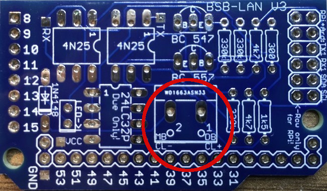
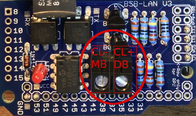
The PCB of the adapter is already labeled with “CL+ / DB” and “CL- / MB”.
If you are building an adapter completely by your own, please look at the schematics.
The plain PCB.
Fully assembled PCB.
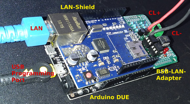
The complete setup (Arduino Due, LAN shield, BSB-LAN adapter), belonging cables included.
BSB:
The connection of the adapter takes places at the already described ports and pins.
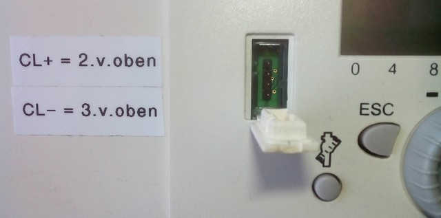
Please connect
“CL+” (adapter) to “CL+” (controller) and
“CL-“ (adapter) to “CL-“ (controller).
An additional pin “G+” which could be found sometimes at the controller is only for the backlight of a QAA75 room unit (because it offers 12V constantly) - please make sure that you DON’T use that pin by accident!
LPB:
The connection of the adapter takes places at the already described ports and pins.
Please connect
“DB (adapter)” to “DB (controller)” and
“MB (adapter)” to “MB (controller)”.
PPS:
The connection of the adapter takes places at the already described ports and pins.
In most of the cases it’s “A6” and “M”, therefore please connect
“CL+” (adapter) to “A6” (controller) and
“CL-“ (adapter) to “M” (controller).
Connectors:
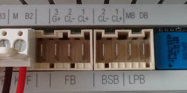
Both the BSB and LPB ports are double-pole and are labeled different sometimes by certain manufacturers. The most common names are:
- BSB port: BSB, FB, BSB & M, CL+ & CL-
- LPB port: LPB, DB & MB
The following pictures show some examples of these connectors at different controllers:
BSB (FB with CL+ & CL-) and LPB (DB & MB) at a Broetje ISR-RVS43.222 controller.
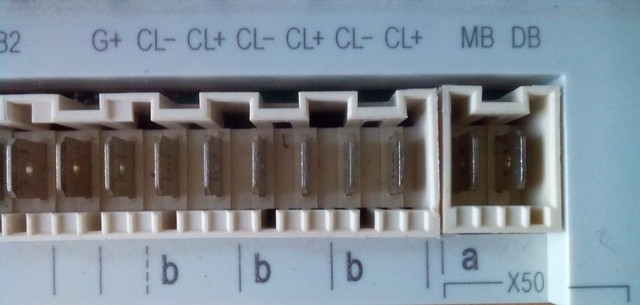
Connectors b = BSB (CL+ & CL-) and a = LPB (DB & MB) at a Siemens RVS63.283 controller.
BSB at connector “FB” at a LMS1x controller.
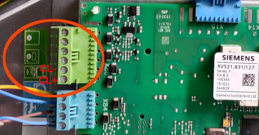
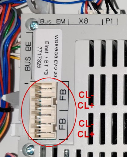
BSB at connector “X86” at a RVS21 controller.
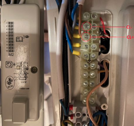
BSB on the “M2” connector block (behind the plastic cover on the left side of the picture) of a Baxi Luna Platinum.
User “olympia” kindly wrote a manual about how to connect it for the Baxi Luna Platinum and made it available on his GitHub account. Many thanks for that!
BSB (CL+ & CL-) at the four pin service plug at the front of the operating unit ISR Plus. The (permament) usage of this connector isn’t advisable though.
| Notes on connectors |
|---|
| The connection of the cables to the respective contacts should always be done with the specific connectors if available. A general list of the respective connectors can’t be named here though, because some controllers need special connectors. For the most common three poled “FB” port (connector for the room unit) which is available at most of the controllers, this connector seem to fit though: Broetje Connector Room Unit ISR, Rast 5- 3pol. = 627528. |
| BSB / LPB / PPS: If the original connectors are not available, (insulated) 6,3mm cable lugs can be used instead. |
| Four pin service plug: For the (temporary) connection at the four pin service plug at the front of the operating unit, 2,54mm DuPont connectors (female) can be used. You can find them (e.g.) at the typical breadboard connection cables or at many cables used within the internal parts of desktop computer hardware (e.g. internal speaker, fan). |
| Notes on cables |
|---|
| LPB: In order to be as protected as possible from interference, the official Siemens document “CE1N2032D Local Process Bus LPB project planning basics” states that the connection cables for the LPB connection should have a cross-section of 1.5mm² in accordance with LPB design principles, twisted two-core and shielded (cable length 250m max per bus node, max total length 1000m). However, it is not mentioned where or how to connect the shield of the cable. |
| BSB: For the BSB connection, Cu cables with a minimum cross-sectional area of 0.8mm² (up to 20m) should be selected, eg LIYY or LiYCY 2 x 0.8. For cable lengths up to 80m 1mm² should be selected, up to 120m 1,5mm² cross section. |
| In general, a parallel installation with mains cables should be avoided (interference signals). |
| Even though these are the official notes, users reported success with cables like phone installation cables, 0.5-0.75mm speaker cables, LAN cable (where two or three wires are connected together to each connector) and so on. Before you have to buy something new, you probably can just give it a try and see if you have some cables already at home which will do the job. |
3.2 Function Test and First Use
To check if the adapter works correctly and recognizes your controller automatically, it’s adviseable to follow these steps:
-
Switch off the controller of the heater and connect the adapter at the right pins to the BSB (or LPB / PPS). Watch the polarity!
-
Switch the controller back on and check if the red LED at the adapter is lit. If you see the LED flackering a little bit from time to time then that’s no malfunction - it schows activity on the bus.
-
Connect the Arduino Due (of course fully assembled with the lan shield and the adapter) via USB (use the “Programming Port” in the center) with your computer and via LAN with your network.
-
Now start the Arduino IDE, choose the right COM port where the Arduino is connected to and start the serial monitor (menu “Tools” or the little magnifying glass symbol at the top right corner).
-
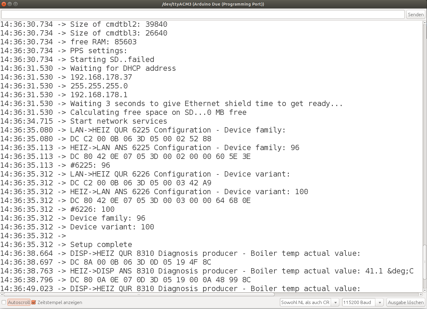
If the connected controller has successfully been detected automatically by BSB-LAN it should appear an output in the serial monitor where the value/number behind “Device family” and “Device variant” is NOT 0.
A correct output looks (e.g.) like that (with different numbers due to a different controller type):
[...]
Device family: 96
Device variant: 100
[...]
The following screenshot shows an output of the serial monitor after a successful start.
The adapter is configured by deafult as “LAN” and queries the parameters 6225 and 6226 initially for autodetection of the controller.
The following lines already are telegrams.
The display of the operating unit of the controller shows the temperature of the boiler unit (here: “Boiler temp actual value”) which comes in periodically as a so called broadcast message (BC).
| Note |
|---|
| If only weird character strings appear in the serial monitor, check the baud rate at the lower right corner of the serial monitor window. It should be set to 115200 baud. |
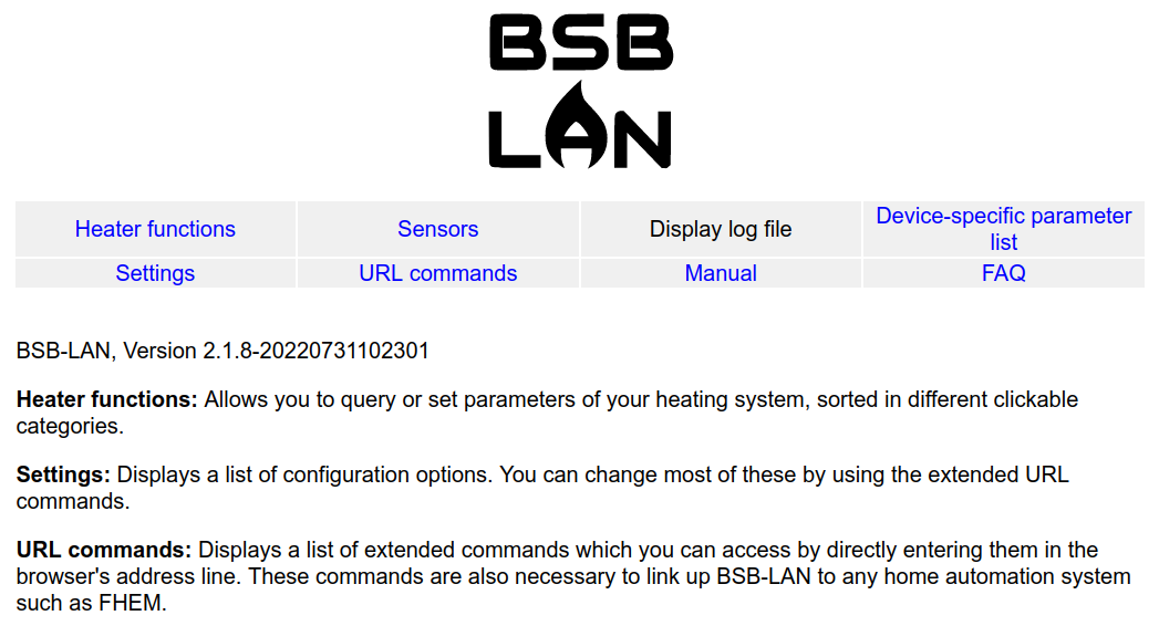
Check if BSB-LAN is accessable
As a first test if you can reach the BSB-LAN server, just enter the specific URL of your BSB-LAN setup (if you are using DHCP, the IP will be shown during startup within the SerMo). You should reach the start page of BSB-LAN:
Next, please proceed with the following chapter.
3.3 Create Device-Specific Parameter List
| Note |
|---|
| The procedure described below applies to controllers that are connected to the BSB-LAN setup via BSB or LPB. If you have connected a controller via PPS, the following is not necessary, because the function /Q is not available for PPS controllers and the creation of a specific file BSB_LAN_custom_defs.h is not necessary! |
| There are also restrictions with controllers that are connected via an LPB that has become available through retrofitting the OCI420 bus module clip in (LMU54/64 and LMU74/75 controllers). Here the corresponding device data should be listed at the beginning, but the “complete dump” is also not available. If this is also the case with LMS14/15 controllers and the newer OCI345 bus module ClipIn isn’t clear yet. |
In the basic version, only very few selected parameters are supported by all controllers (e.g. time, device identification, comfort temperature heating circuit 1, outdoor temperature). However, in order to get complete access to your specific controller, a suitable BSB_LAN_custom_defs.h file must first be created, which contains exactly the parameters that your controller has!
To generate the text file needed to create the BSB_LAN_custom_defs.h file, click on the “Controller-specific parameter list” button at the top of the web interface and then on “Download” at the bottom.
Attention: This query takes a while - please wait until the whole ‘complete dump’ or download of the text file is finished!
This function now queries all available parameters of the connected controller and saves the result in a text file.
This text file must then be sent to Frederik (bsb(ät)code-it.de), from which the device-specific file BSB_LAN_custom_defs.h for the connected controller will be generated. Please also specify the language version you want to use for BSB-LAN later (i.e. German or English).
After you have received this file from Frederik, you have to replace the previous BSB_LAN_custom_defs.h with this one and reflash BSB-LAN once. Only then you have complete access to all functions of your controller!
| Note |
|---|
| The device-specific parameter list should only be called up via the bus system that will be used later! If there is an LPB network, the device-specific list must also be called up via LPB, as otherwise not all parameters of all controllers will be transmitted. |
| Once a list has been created, it retains its functionality even when BSB-LAN is updated. It is therefore not necessary to create a new list as long as no controllers have been replaced or added. |
| In an LPB network, the category list is taken from the main device. However, parameters from other controllers in the network can be called up directly by addressing them using the exclamation mark (see URL commands), even if they do not appear in the category list. |
| Only the parameter definitions of the controller are queried, in no case configuration settings are read, set or changed! |
Alternatively, you can find the BSB_LAN_custom_defs.h which was used in previous versions of BSB-LAN in release version 2.2. However, since this parameter list is missing hundreds of parameters from newer devices and contains a lot of ambiguities and sometimes also errors, its use is not recommended and should only be done after carefully examining the parameters you want to use. |
3.4 Debugging and Troubleshooting
If, contrary to expectations, problems occur and the BSB-LAN setup is not usable, this can have several causes.
As a first step it is always a good idea to check the cabling and see if the red LED on the BSB-LAN adapter is lit.
As a further step it is always useful to connect the microcontroller additionally to the PC and to start the Serial Monitor (SerMo) of the Arduino IDE. There you can check the startup process. If only cryptic strings appear in the output, check the set baud rate (bottom right). This should be set to 115200 baud.
If the connected controller is not automatically recognized correctly, there is a “0” at “Device family” and “Device variant”, additionally there are six lines “query failed” in front of “Device family”.
Example:
[...]
query failed
query failed
query failed
query failed
query failed
query failed
Device family: 0
Device variant: 0
[...]
Mostly the reason is then a problem of the hardware setup or the cabling, because the parameters 6225 and 6226 could not be retrieved successfully (error message “query failed””).
Further reasons for malfunctions are listed in chapters 13, 14 and 15.
