6. BSB-LAN: Special Functions
6.1 Logging Data
Insert a FAT32-formatted microSD card into the memory card slot of the ethernet shield before powering up the microcontroller.
Before flashing, activate the definement #define LOGGER in the file BSB_LAN_config.h, add the parameters to be logged to the variable log_parameters and determine the log interval with the variable log_interval. Please also note the corresponding points in chapter 5.1.
Later, during the runtime, both the interval and the logging parameters can be changed by using the command "/L=[Interval],[Parameter1],...,[Parameter20]".
If an Olimex ESP32-EVB is used (or a microSD card adapter is used on an ESP32-based board) and the logged values are to be written to the microSD card instead of the flash memory (which is highly recommended!), then the following definition must be activated in the BSB_LAN_config.h file: #define ESP32_USE_SD.
All data is stored within the file datalog.txt on the card in csv format. Thus the data can easily be imported in Excel or OpenOffice Calc.
The file contents can be viewed with the URL command /D, a graphical representation of the log files is done by /DG.
To delete and rebuild the file datalog.txt, use the URL command /D0.
The URL command /D0 should also be executed on first use! This will initiate the file with the appropriate CSV header.
| Notes |
|---|
| Occasionally it may happen that certain microSD cards are not easily recognized by the LAN shield. If an error occurs, you’ll get a warning message. In that case please try a different card which is as up to date as possible. |
| Please note that the microcontroller is not an exact clock. Even if the interval has been set up to e.g. 60 seconds, the time displayed in the file (which is received by the heating control) possibly will differ - this can take up to a second per minute. If an exact log time is absolutely necessary, you can measure the average time difference between the microcontroller time and the real time and adjust the log interval accordingly (e.g. set 59 seconds instead of 60 seconds). |
In addition to the use of complex systems such as FHEM and the specific logging solutions, you can e.g. execute the following command periodically (for example via cron job):
DATE=`date +%Y%m%d%H%M%S`; wget -qO- http://192.168.178.88/8310/720/710 | egrep "(8310|720|710)" | sed "s/^/$DATE /" >> log.txt
The log file log.txt resulting from this example contains the
recorded values of parameters 8310, 720 and 710.
Later you can sort the log file based on the parameter numbers, use the command 'sort' for this:
sort -k2 log.txt
6.2 IPWE Extension
The IPWE extension offers the presentation of various previously defined parameters by the usage of just one short URL. To access this table overview, the following URL has to be used:
<ip-address>/ipwe.cgi.
| Note |
|---|
| If the optional security function of the passkey is used, the passkey has NOT to be added within the URL in this case! |
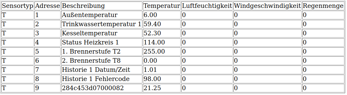
Example of an IPWE output.
To use the function of the IPWE extension, one has to make two settings in the file BSB_LAN_config.h before flashing the microcontroller:
- The definement
#define IPWEhas to be active. - The desired parameters which should be displayed have to be listed.
Additionally to the set parameters, the values of optional connected sensors (DHT22 / DS18B20) will be listed automatically.
If DS18B20 sensors are connected, the specific sensor id of each sensor will also be displayed. You can see this in the last row of the IPWE example above, the specific sensor id of the one and only connected DS18B20 sensor is “284c453d07000082”.
| Notes |
|---|
| If there are -by accident- parameters defined which aren’t supported by the specific heating system, the non-existent values will be displayed as “0.00”. So don’t get that wrong - it doesn’t mean, that that specific value is “0.00”! Before you define the parameters, it’s best to check before and make sure, that the heating system really offers these parameters. |
| Because the IPWE extension was originally designed to implement values of a specific wireless weather station, there will be some columns which doesn’t seem to make sense, like “Windgeschwindigkeit” (wind speed) or “Regenmenge” (amount of rain water) - you can just ignore that. Basically, there are just two columns which are relevant for the normal parameters: “Beschreibung” and “Temperatur”, because here you can find the name of the parameter and the belonging value. |
| The states of certain parameters aren’t shown in clear text, only in numerical values. In the above example you can see this e.g. in the row with the parameter “1. Brennerstufe T1”: There doesn’t appear “Ein” (on), it only shows the value “255” - which means “Ein” (on). |
6.3 Transmitting a Room Temperature
By using an INF-message, a room temperature can be transmitted to the controller.
Therefore you have to activate the function ‘room influence’ (e.g. parameter 750 for circuit 1, parameter 1050 for circuit 2) before.
Write-access has to be granted for BSB-LAN.
The room temperatures have to be sent regularly in a ‘short’ interval, like every one or two minutes.
| Note |
|---|
| This parameter can’t be queried. |
The following parameters have to be used:
- 10000 = heat circuit 1
- 10001 = heat circuit 2
- 10002 = heat circuit 3/P
Example:
This command transmits a room temperature of 19.5°C to the circuit 1: http://<ip-address/I10000=19.5
Excursus: room influence regarding the room temperature
FHEM forum user “freetz” has decoded the model behind the “room influence” (parameter 750), so that the effects on the flow temperature became more clear. Thanks a lot for this!
His article (German language) as well as an Excel spreadsheet can be found here.
6.4 Simulating the Presence Function
The function of the presence button (which can be found at the room units) is implemented as the parameter “Heating mode (temporary)” with the special parameters
- 10110 = heating circuit 1
- 10111 = heating circuit 2
- 10112 = heating circuit 3
and has to be executed as a SET-command.
This function can be used in automatic mode to switch between comfort and reduced heating modes within the time program. The respective switchover is valid until the next switchover takes place according to the time program (or by using the presence button again).
With an active automatic operationg mode one has to use
http://<ip-address>/S<parameter>=1 to change to the heating mode ‘reduced’ and
http://<ip-address>/S<parameter>=2 to the change to the heating mode ‘comfort’.
Example:
The command <URL>/S10110=2 switches HC1 to the heating mode ‘comfort’ within the operating mode ‘automatic’, <URL>/S10110=1 switches HC1 to the heating mode ‘reduced’.
| Notes |
|---|
| The above listed parameters must be writeable, therefore BSB-LAN needs write-access (see chap. 2.2). |
| These special parameters (10110, 10111, 10112) can not be queried! |
| The function of the presence button is only available when the heater is in operating mode ‘automatic’! |
| The respective change is valid until the next changeover of the heating mode according to the time program. |
| For users of BSB-LAN version v3.x, in whose controller-specific file BSB_LAN_custom_defs.h this command is not yet implemented, it can be added manually afterwards. A corresponding description of the necessary steps can be found in chap. 2.3. |
6.5 Triggering a Manual DHW-Push
Within many controllers there is a (nearly) undocumented function available: a manual DHW push. To initiate a manual DHW push, one has to press and hold the DHW-mode-button at the operational unit. After approx. three seconds a message appears at the display and the heating process starts.
With some controllers this function can also be used with BSB-LAN using a SET-command: http://<ip-address>/S10019=1 - of course the parameter 10019 must be made settable before (see chapter 2.2).
6.6 Changing the Date, Time and Time Programs
Changing the date, time and time programs is only possible by using a special URL command, it is not possible via webinterface.
To use this feature, BSB-LAN needs write access (see chapter 2.2).
Changing the date and time
The following URL command sets the date to the fourth of january 2019 and the time to 08:15pm:
/S0=04.01.2019_20:15:00
Using this function it is possible to sychronize the time with (e.g.) a NTP time server.
Changing time programs
The following URL command sets the time program for wednesday at heating circuit 1 (parameter 502) to 05:00am-10:00pm:
/S502=05:00-22:00_xx:xx-xx:xx_xx:xx-xx:xx
Deleting a time program
To delete a time program, you must enter “128:00” as the time.
So if, for example, three time programs have been set for Tuesday and you only want to keep the first one from 5-22h, the following command must be used:
/S502=05:00-22:00_128:00-128:00_128:00-128:00
6.7 Transmitting an Alternative Outside Temperature
Certain specific controller types allow the usage of different wireless components. Amongst other things there is also a wireless outside temperature sensor available. Within these compatible controllers it is possible to use BSB-LAN to transmit an alternative outside temperature.
Until now it seems that only controllers of the types LMS and RVS are compatible. Older types of controllers (e.g. LMU and RVA) don’t seem to be compatible.
For using this function the wired temperature sensor has to be deconnected from the controller. The transmission of the alternative outside temperature has to be done regularly within a time windows of (approx.) max. 10 minutes, but it is adviseable to transmit the value every 60 to 120 seconds.
To use this function, BSB-LAN needs write access (see chap. 5). The outside temperature has to be transmitted as an INF message (with the virtual parameter 10003) using the URL command
<ip-address>/I10003=xx
where xx is the outside temperature in °C (degrees celcius); fractional values are possible.
Example:
With <ip-address>/I10003=16.4 the outside temperature of 16.4°C is transmitted; <ip-address>/I10003=9 transmits 9°C.
6.8 Integrating Own Code in BSB-LAN
BSB-LAN offers the possibility to integrate your own code.
For this purpose, the corresponding definition in the file BSB_lan_config.h must be activated and the code must be added in the files BSB_lan_custom.h, BSB_lan_custom_global.h and BSB_lan_custom_setup.h.
Examples can be found in the “custom_functions” folder.
Please read the corresponding Readme for more information.
FHEM-Forumuser “Scherheinz” has provided another example (see forum post).
Many thanks for this!
In the following the above mentioned example:
Description:
“Every 20 seconds the battery voltage is read in via a voltage divider. Then a moving average is calculated from the last 10 values and forwarded to FHEM via MQTT” (quote from the above linked post).
Integration:
The following code must be inserted into the file BSB_lan_custom_global.h:
const int akkuPin = A0;
int akkuWert = 0;
float akkuSpg = 12.00;
char tempBuffer[100];
int j;

void Filtern(float &FiltVal, int NewVal, int FF){ //gleitender Mittelwert bilden aus den 10 letzten Werten
  FiltVal= ((FiltVal * FF) + NewVal) / (FF +1);
}
The following code must be inserted into the file BSB_lan_custom.h:
if (custom_timer > custom_timer_compare + 20000) {    // alle 20 Sekunden
  custom_timer_compare = millis();

akkuWert = analogRead(akkuPin); // Spannung messen

akkuWert = map(akkuWert, 500, 1023, 0, 150); // umwandeln auf 0 - 15V
akkuWert = akkuWert / 10.00;

Filtern(akkuSpg, akkuWert, 9); //gleitender Mittelwert bilden aus den 10 letzten Werten
if (j++ > 10) akkuWert=1;  // nach 10 Werten Sprung auf 1

if (!MQTTClient.connected()) {
      MQTTClient.setServer(MQTTBroker, 1883);
      int retries = 0;
      while (!MQTTClient.connected() && retries < 3) {
        MQTTClient.connect("BSB-LAN", MQTTUser, MQTTPass);
        retries++;
        if (!MQTTClient.connected()) {
          delay(1000);
          DebugOutput.println(F("Failed to connect to MQTT broker, retrying..."));
        }
        MQTTClient.publish("AkkuSpannung",dtostrf(akkuSpg, 6, 1, tempBuffer));
        MQTTClient.disconnect();
      }
    }
}
6.9 Using the Webserver Function
The webserver function has been developed and added by the user “dukess”, who also gave the following informations about the usage.
Thanks a lot!
By activating the belonging definement ‘#define webserver’ within BSB_LAN_config.h, BSB-LAN can act as a webserver which even supports static compression. For using that function, a few points must be noticed:
- All files are / must be stored on the microSD card, but files can be placed in different directories and subdirectories though. E.g.:
http://<bsb-lan-ip-address>/foo/bar.htmlgets the filebar.htmlfrom the directoryfooof the microSD card. - Only static content is supported.
- Supported file types are: html, htm, css, js, xml, txt, jpg, gif, svg, png, ico, gz.
- The web server supports the following headers: ETag, Last-Modified, Content-Length, Cache-Control.
- As already mentioned, the web server supports static compression. If possible (if the client’s browser supports gzip), it’s always trying to deliver gzipped content (e.g. /d3d.js.gz for the URL /d3d.js).
The following examples show the usage:
- If there’s no file named
index.htmllocated in the root directory of the microSD card, the regular web interface of BSB-LAN will be displayed by the query of the URLhttp://<ip-address>/. - If there’s a file named
index.htmllocated in the root directory of the microSD card, that file will be displayed by the query of the URLhttp://<ip-address>/instead of the regular webinterface of BSB-LAN. - If the file
index.htmlis located in a subdirectory of the microSD card, that file will only be displayed when the complete URL will be queried:http://<ip-address>/foo/bar/index.html. If (in this case) onlyhttp://<ip-address>/foo/bar/would be queried, the regular webinterface of BSB-LAN would still be displayed, because directory listing or URL rewriting isn’t implemented in the special webserver function.
| Note |
|---|
| If you are using the PASSKEY function, you have to add the passkey to the URL. |
6.10 Using the Alternative AJAX Web Interface
The AJAX webserver function has also been developed and added by the user “dukess”.
Please see the informations in his AJAX repo for usage.
Thanks a lot!
6.11 Room Unit Emulation
With the setup of the BSB-LAN adapter a room unit can be emulated, therefore additional hardware is needed.
The following functions are implemented in the code:
-
Integration fo connected sensors for measuring and transmitting the room temperature(s) to the desired heating circuit(s),
-
triggering a DHW push by using a pushbutton and
-
using the presence function for the heating circuits 1-3 by using a pushbutton (automatic detection of the present state with the corresponding change between comfort and reduced mode in the automatic mode).
To use the functions, the corresponding entries must be made in the configuration. This can be done either by changes in the file BSB_LAN_config.h or via the web interface (menu item “Settings”).
In the following some notes about each function.
Room temperature
- Up to five connected sensors can be specified for the room temperature measurements.
- If more than one sensor is used, an average value is automatically calculated and transmitted to the heating controller.
- To assign the respective sensors to the desired heating circuits, the specific parameter numbers of the respective sensors must be entered. An overview of the connected sensors together with the associated parameter number can be found in the category “One Wire, DHT & MAX! Sensors” (menu item “Heating functions” or by clicking on the menu item “Sensors”).
- When entering several sensors for one HC, the parameter numbers are only to be separated from each other by a comma, no space may be used after the comma.
Pushbutton for TWW push and presence button function
- The GPIO pins used for connecting the pushbuttons (one pin per pushbutton) must be set in the configuration.
- DIGITAL pins must be used!
- Please make sure that you do not use any other pins (e.g. those of connected sensors)! For Due-users: explicitly don’t use the pins 12, 16-21, 31, 33, 53!
- The pushbuttons are to be connected microcontroller-typically for HIGH, that means you must connect a pull-down resistor (approx. 100kOhm) additionally to the respective pin.
- You can find a pinout diagram of the Due in appendix B.
- If you are not sure how to connect a pushbutton to an microcontroller for HIGH, please have a look at the internet, where you can find countless examples.
Nevertheless, it should be briefly mentioned here how to proceed:- The push button with the two connectors A and B has to be connected at one connector (A) to the desired GPIO digital pin of the Due.
- Additionaly, to the same terminal of the pushbutton (A) the pull-down resistor has to be connected, which in turn has to be connected to GND of the Due.
This is important, the use of the resistor must not be omitted! Due to the pull-down resistor a defined potential is applied to the GPIO when the button is not operated and the so-called ‘floating’ of the input is prevented. If the pull-down is not used and the input would ‘float’, unwanted level changes could occur at the pin, which in turn would result in the respective function (DHW push or heating mode switchover) being triggered unintentionally. - The other pin of the button (B) is connected to a 3.3V pin of the Due.
Caution: The inputs of the Due are only 3.3V tolerant, so don’t ever connect the pushbutton to a 5V pin of the Due!
If the button is pressed now, the circuit is closed - the signal is recognized as HIGH and the respective command (TWW push/presence button) is triggered.
- Additional note: If you disconnect the pushbutton(s) (e.g. because you don’t want to use them anymore) make sure that you set the belonging pin to “0” again and save the changed configuration, so that no floating could occur at that previously used pin!
6.12 Erasing EEPROM Using Pincontacts
In principle, the EEPROM can be erased via the web interface with the command /NE. However, in certain situations (e.g. if no access to the web interface is possible) it may be necessary to delete the EEPROM without using the URL command.
For this, the following pins must be connected to each other when starting or rebooting the device:
- Due: pins 31 & 33
- ESP32: pins 18 and GND
- Olimex: pins 34 and GND
After successful erase, the LED of the Arduino/ESP32 flashes for four seconds.
At restart the (pre-)settings from the file BSB_LAN_config.h are taken over, an adjustment can be done afterwards as usual via (e.g.) the web interface.
The above mentioned pins for erasing can also be set individually in the file BSB_LAN_config.h via the definition #define EEPROM_ERASING_PIN XX if required.
Alternatively, the microcontroller can also be connected via the serial interface and the character string /NE can be sent via the serial monitor, if necessary with a preceding passkey (e.g. /1234/NE ). Then the EEPROM will also be erased.
ESP32 users can also set the entry “Erase All Flash Before Sketch Upload” in the ArduinoIDE under “Tools” to “Enabled”, then the entire flash area is erased once before the upload.
