7. BSB-LAN Setup: Optional Hardware
The BSB-LAN setup can be extended in its range of functions by optional hardware. In the following some components such as sensors and relays as well as further hardware solutions are presented.
If you have implemented your own interesting project that works with the BSB-LAN setup and extends its functionality and you would like to share it with other users, please contact me (Ulf) by email (adapter (at) quantentunnel.de)!
| ATTENTION, important note: |
|---|
| When connecting optional hardware like sensors, relays etc. to the Arduino Due or the specific ESP32 board you have to make sure that the used pin is not used elsewhere or is not already used internally! Information about the pin assignement can be found in the respective pinout scheme of the specific Arduino-/ESP-board. Also pay attention to the serial pins of the adapter and additional components like a LAN-shield, a relay-shield etc. |
7.1 Usage of Optional Sensors: DHT22, DS18B20, BME280
There is the possibility to connect additional sensors directly to certain pins of the adapter or the microcontroller:
- DHT22 (temperature, humidity; parameter numbers 20100-20199)
- DS18B20 (OneWire sensor: temperature; parameter numbers 20300-20399)
- BME280 (temperature, humidity, pressure; parameter numbers 20200-20299)
The necessary libraries for the Arduino IDE are already included in the repository of the BSB-LAN software.
If you are using an ESP32 board, there is also a (unofficial) possibility to use Xiaomi Mijia BLE sensors. Please see chap. 7.4.4 for further informations.
| Notes |
|---|
In the default configuration of BSB-LAN “Pin 0” is set for all sensors. This corresponds program-internally to the deactivation of this function and designates not the pin GPIO0! After connecting a sensor the corresponding pin must be set in the configuration of BSB-LAN - for this the GPIO pin number must be entered (e.g. 7 for the connection of a sensor to GPIO7). The localizations and designations of the pins are to be taken from the board-specific pinout scheme. |
Usually, the sensors can be connected to GND and +3,3V of the adapter/microcontroller (by usage of the necessary additional pullup-resistors!).
For the usage of these sensors, one has to activate the belonging definements in the file BSB_LAN_config.h and has to set the specific pins which are used for DATA (also see chapter 5). Make sure you don’t use any of the protected pins listed in the file BSB_LAN_config.h!
After successful installation you can access the values of the sensors either by clicking at the button “sensors” at the top of the webinterface, by clicking at the category “One Wire, DHT & MAX! Sensors” or by using the url command with the specific number of that category.
Besides that, they are also displayed in the IPWE extension by default, which can be accessed by using the URL <ip-address>/ipwe.cgi. For using the IPWE extension, one has to activate the belonging definement in the file BSB_lan_config.h though.
If you want to log the measured values or if you want to create 24h average calculations, you can realize that by adjusting the belonging parameters in the file BSB_LAN_config.h.
7.1.1 Notes on DHT22 Temperature/Humidity Sensors
DHT22 sensors are often advertised as “1 wire”, but they are NOT part of the real OneWire bus system by Maxim Integrated and aren’t compatible with these components.
Furthermore they are not even part of any real bus system, because the sensors don’t have any specific sensor id and can’t be connected to the same DATA-pin if you are using more than one sensor.
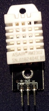
Usually these sensors have four pins, but only three of these are connected internally. Most in the time it’s the third pin from the left (when viewed from the front) which isn’t connected, but you should verify this before soldering.
The most common pinout is:
- Pin 1 = VCC (+)
- Pin 2 = DATA
- Pin 3 = usually not connected
- Pin 4 = GND (-)
When you connect the sensor, an additional pullup resistance has to be placed between VCC (pin 1) and DATA (pin 2) which should be in the range between 4,7kΩ to 10kΩ. In most cases a value of 10kΩ is suggested, but this should be determined individually (especially if any problems with the sensor occur).
| Please note: |
|---|
| If more than one DHT22 sensor should be used, you have to use an own pin at the microcontroller for each DATA pin of the sensor. Furthermore you have to define them in the file BSB_LAN_config.h. |
Besides the ‘plain’ sensors there are models which are already soldered onto a little circuit board, where the three necessary pins are lead out and labeled. The following picture shows one of these types with the identical sensor AM2302.
The query of the sensors/measured values can be done either via direct parameter call (URL/20100-20199) or by calling the corresponding category. The following screenshot shows the web output of a connected DHT22 sensor.
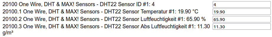
Display of the measured values of a DHT22 in the web interface (category “One Wire, DHT & MAX! Sensors”).
| Note: |
|---|
| You can find various tutorials and examples within the internet about the installation and usage of DHT22 sensors. |
7.1.2 Notes on DS18B20 Temperature Sensors
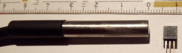
Sensors of the type DS18B20 are ‘real’ 1-wire/OneWire components of Maxim Integrated (initially Dallas Semiconductor).
Each sensors has a unique internal sensor id which allows the clear identification of a certain sensor within a more complex installation of the bus system - if you wrote down the specific id for each sensor.
Besides the regular TO-92 type they are also available as waterproof capsuled types, which already have a cable connected.
Especially for the usage within heating system installations the capsuled type is very interesting, because you can realize an individual (and waterproof!) installation easily and const-effective.
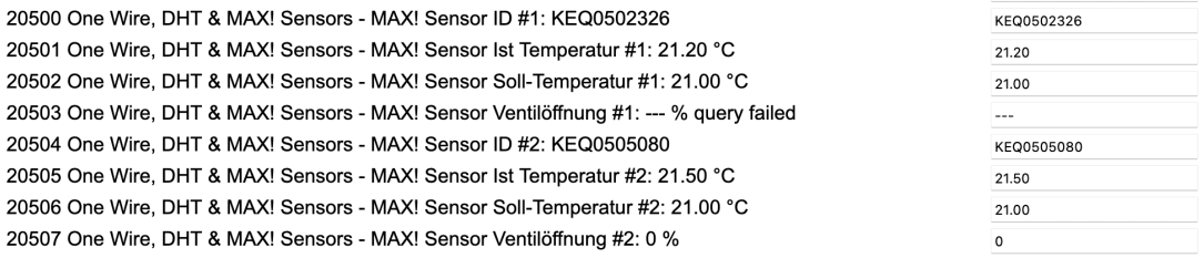
The query of the sensors/measured values can be done either via direct parameter call (URL/20300-20399) or by calling the corresponding category. The following screenshot shows the web output of four DS18B20 sensors connected to pin 7.
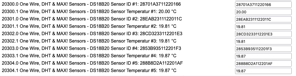
Display of the measured values of four DS18B20 in the web interface (category “One Wire, DHT & MAX! Sensors”).
| Note: |
|---|
| If you are using DS18B20 sensors, the specific sensor id of each sensor will also be listed within the output of the category sensors (and the output of the IPWE extension, if used). Especially if more than one sensor will be added to the system, these unique sensor ids are necessary to identify a specific sensor later. So if you integrate BSB-LAN and/or these sensors in your home automation software, you should consider this (e.g. use RegEx on the sensor ids). |
| It’s adviseable to read out the sensor id (e.g. by using /K49) and label each sensor, so that you don’t get confused later. For this, you can raise or lower the temperature of one sensor (e.g. hold it in your hand) and query the category sensors again after a certain time. Now you can see the changed value of one sensor and write down the specific sensor id. |
| Besides that, if any sensor will be exchanged or added, most of the time the displayed order (within the output of the category sensors or the IPWE extension) of the sensors will change also, because internally they are listed following the specific sensor ids. So if you only adjust the reading following the order and name the sensors like that, it can happen, that the belonging name doesn’t show the correct sensor anymore. The following screenshots show this circumstance. |
| If any changes within the installation of the sensors occur (e.g. if you exchange, add or remove something), you have to reboot the Arduio, so that the sensors will be initially read out and added to the software. |
Notes on the electrical installation:
Each sensor usually offers three pins: VCC, DATA and GND.
Within the capsuled types, the colors of belonging wires are often as follows:
- Red = VCC (+3,3V)
- Yellow = DATA
- Black = GND (-)
If you are using more than one sensor and/or larger cable lengths, it’s advisable to add a 100nF ceramic capacitor (and maybe also an addditional 10µF tantal capacitor) for each sensor. The capacitors should be added as close as possible to the sensor and need to be connected between GND and VCC so that a brownout at the time of the query will be compensated.
Besides the (optional but advisable) usage of capacitors, you have to use a pullup resistance (only one!) at the output of the adapter/microcontroller and place it between DATA and VCC (+3,3V). If you are using more than one sensor and/or larger cable lengths, you probably have to evaluate the correct dimension of the resistor, which can be smaller than the 4,7kΩ which is suggested most of the times.
Furthermore, in more complex or larger installations, it seems in individual cases that the voltage supply with the 3.3V of the Due does not always allow a problem-free operation of the sensors. Since these OneWire sensors are “open drain”, they can also be operated with 5V of the Due, which seems to result in a more stable operation. However, it must then be ensured that the 5V is never applied to the GPIO of the Due!
For the installation this means that VCC of the sensors is connected to the 5V pin of the Due, but the PullUp resistor to be used must be placed between DATA and a 3.3V pin of the Due!
Notes:
- If you are using the mentioned capsuled and already wired types, it’s usually sufficient to place the capacitors where the wires will be connected. So you don’t have to cut the wires at the capsule to place the capacitor there (according to experience, at least with the types which come with a cable length of 1m or 3m it’s not necessary).
- In contrary to ceramic capacitors you have to pay attention to the correct polarity if you are using additional tantal capacitors!
- It’s not advisable to use the ‘parsite power mode’.
- It’s advisable to use a shielded cable for the connection. The shield should be connected to GND at one end of the cable.
- To minimize the risk of electrical interference, try not to lead the cable parallel to power cords. Besides that, you can also add a ferrite ring to minimize the risk of electrical interference which maybe can come from the power supply of the microcontroller. Just lead the cable a few times through the ferrite ring.
If you have to use larger cable lengths, it’s necessary to pay attention to the correct network topology. Have a look at the tutorial which was written from the manufacturer: “Guidelines for Reliable Long Line 1-Wire Networks”.
Note:
You can find various tutorials and examples within the internet about the installation and usage of DS18B20 sensors.
Summary of needed parts for an installation:
- three-wired cable (if shielded, connect the shield at one end to GND)
- one pullup resistance 4,7kΩ or maybe smaller, positioned between VCC and DATA at the adapter/microcontroller
- ceramic capacitor 100nF, one for each sensor, positioned between VCC and GND close to the sensor
- optional: tantal capacitor 10µF, one for each sensor (additional to the ceramic capacitor!), positioned between VCC and GND close to the sensor (please pay attention to the correct polarity!)
- optional: screw terminals, circuit board, housing, …
Notes for the usage within your heating system installation:
- If you want to use the capsuled types of sensors, especially within bigger installations it can be adviseable to use the version with 3m cable instead of 1m cable. They are only a little bit more expensive but offer a greater freedom of movement when you want to place the sensors.
- If you want to place the sensors at some pipes, it’s adviseable to create a little bed made of thermal paste for the contact area. Fasten the sensor with a metal pipe clamp to the pipe and also fasten the cable itself with a cable tie, so that tensile forces won’t work on the sensor itself and that the sensors stays in place. Of course you need to place the sensor between the pipe an the insulation and close the insulation after you are done with the installation. If there is no pipe insulation it’s advisable to -at least- cover the sensor with a piece of insulation, so that it’s not affected by any cold air or so.
- In general, the sensors should me mounted one or two meters away from a heat source, so that they aren’t affected by that.
Please note:
Already installed sensors which belong to the heating system (e.g. sensors for a warm water tank or a heating buffer tank) are always more important than any sensor for your home automation system! The given installation of your existent heating system should never be adversely affected by any optional installed DS18B20 sensor!
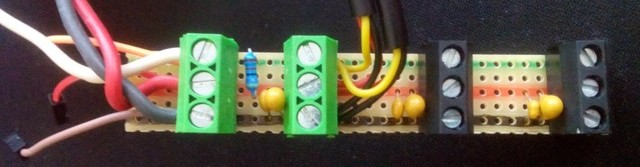
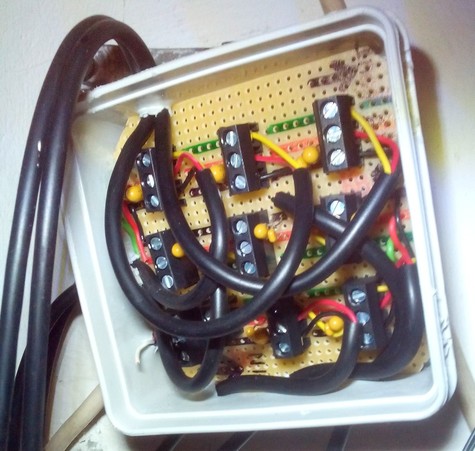
Construction plan:
If you want to set up an installation with more than one sensor and the common capsuled sensors with 1m or 3m cable length, you can build a little ‘distribution box’. For this, you can solder the connection wires of the sensors and the belonging capacitors in line onto a circuit board. If you use screw terminals instead of soldering the sensors straight to the board, you can easily add or exchange sensors later. At the ‘beginning’ of this board, you connect the cable which leads to the adapter/microcontroller. The following pictures show two of these little ‘distribution boxes’ I made - they work perfectly.
7.1.3 Notes on BME280 Sensors
Sensors of the BME280 type offer three (or five) measured variables: Temperature, humidity (plus the calculated absolute humidity) and air pressure (plus the calculated altitude). They are small, usually uncomplicated to connect and provide (sufficiently) accurate measurement results.
Up to two sensors of the type BME280 can be connected to the I2C bus of the microcontroller (also to the deprecated Arduino Mega 2560).
To use them, the corresponding definition in the file BSB_LAN_config.h must be activated and the number of connected sensors must be defined (see chapter 2.2.2).
| Notes |
|---|
| In principle BME280 can also be connected to an SPI, but not at the microcontroller of our BSB-LAN setup! |
| If you need more than two BME280 sensors, you can use an I2C multiplexer TCA9548A for that. |
| You can also use a BMP280. It doesn’t offer humidity measurements though, so we recommend using a BME280. |
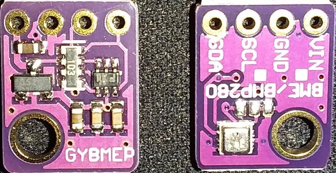
A BME280 sensor on a typical breakout board (clone); left = front, right = back.
The following points must be observed:
- Make sure that the sensor is of type BME280 (and not e.g. a BMP280, BMP180,..).
- Make sure that you use a module that already has pull-up resistors on the breakout board (like on the picture above). If your variant does not have pull-up resistors installed, you have to add them when connecting it to the microcontroller (approx. 10kOhm, connect between SDA and 3.3V and between SCL and 3.3V)!
- Make sure that the first sensor has the I2C address 0x76! This is usually the case with the module shown above.
- The second sensor must get the address 0x77. How to do this on the module shown above is described below.
- Make sure you connect the sensor to the 3.3V pin of the microcontroller! The module shown above has a voltage regulator and level shifter built in, so in this case you could connect it to 5V - but to make sure that there is never 5V at SDA/SCL, you should always prefer to connect it to 3.3V.
Connection
The breakout board is usually already clearly labeled, so the connections can be clearly identified here.
Depending on the microcontroller used, a different I2C connector must be used:
- The Arduino Due has two I2C bus connections: SDA/SCL at pins 20/21 and SDA1/SCL1. Care must be taken to use the SDA1 & SCL1 connectors, as the BSB-LAN adapter already uses the SDA/SCL connectors. SDA1/SCL1 are located next to the “AREF” pin. They are usually covered by the LAN-Shield and are not carried out upwards to/through the LAN shield. However, they are accessible below the LAN shield directly on the Due. For an exact positioning of SDA1/SCL1 please have a look at the pinout diagram in appendix B.
- The Arduino Mega 2560, on the other hand, has only one I2C bus connector: SDA/SCL on pins 20/21. This is not occupied by the old adapter v2, the connector can be used for the BME280.
The wiring has to be done as follows:
| BME280 | DUE | Mega2560 |
|---|---|---|
| VIN | 3,3V | 3,3V |
| GND | GND | GND |
| SDA | SDA1 | SDA 20 |
| SCL | SCL1 | SCL 21 |
Addressing
Common breakout boards like the BME280 module shown above have three solder pads on the front side below the actual sensor, where usually the left and the middle solder pad are connected by a conducting path. This usually corresponds to the address 0x76. The following picture shows this connection circled in yellow.
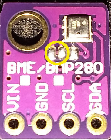
Address 0x76: trace between the left and the middle solder point.
If you want to connect a second sensor in parallel, you have to cut this conducting path carefully(!) and conscientiously with a fine sharp object (e.g. cutter, scalpel). After that the right and the middle pin have to be connected by some solder. The following picture shows the necessary steps: the red line on the left marks the necessary ‘cut’ on the board, the green line on the right marks the connection to be made afterwards using solder.
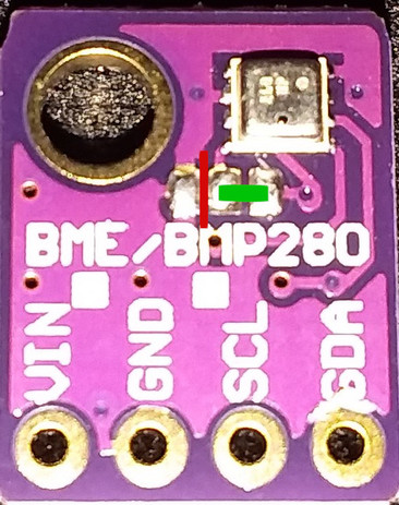
Address 0x77: The red line marks the cut trace, the green line marks the new connection to be made.
Readout
The measured values of the connected BME280(s) can be read out as usual, e.g. by calling up the category “One Wire, DHT & MAX! Sensors” under “Heating Functions”, by a direct click on the button “Sensors” or also by entering the specific parameter numbers. BME280 sensors can be found in the number range ‘URL/20200-20299’. If a logging, a display within the IPWE extension etc. should be done, the specific parameter numbers of the desired measured values of the respective sensor have to be used.
The following screenshot shows the corresponding display of a BME280 within the category “One Wire, DHT & MAX! sensors”.
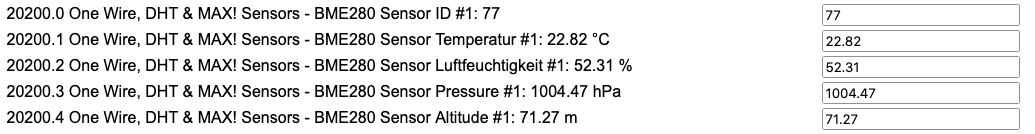
Display of the measured values of a BME280 in the web interface (category “One Wire, DHT & MAX! Sensors”).
7.2 Relays and Relayboards
In principle it’s possible and already provided in the BSB-LAN software as a function with the variants of the URL command /G that additional relays or relay boards can be connected to the Arduino/ESP32 and controlled with BSB-LAN. In this way not only consumers can be switched, but also states of connected consumers can be queried.
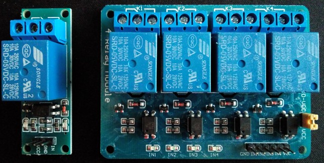
A single and a 4-channel relaymodule for the usage with an microcontroller.
The often cheap relaymodules available for the usage with an microcontroller are often already supplied with a relay which can handle high voltage like 125V or 230V. However, due to poor quality or just an overload, different risky damage can occur. Because of that one should consider to (additionally) use common couple or solid state relays which are used by electricians. in that case one should see the specific data sheet to confirm that the electrical current of the microcontroller is strong enough to trigger the swithcing process of the relay.
| Attention |
|---|
| Electrical installations should only be done by an electrician! High voltage like 230V or 125V can be deadly! It’s adviseable to already include an electrician at the state of planning. |
| Before using a relay/relay board, make sure that it is suitable for the desired task! For the switchable multifunctional inputs of the heating controllers, for example, it is often required that the relay is suitable for low voltage or current - not all relays meet this criterion! |
| It is NOT possible to connect the microcontroller directly with the multifunctional inputs of the controller! |
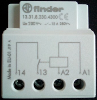
A common coupling relay. At this specific type, the corresponding pins at the microcontroller have to be connected with “14” and “13”.
| Example |
|---|
| If the controller of a solarthermic installation isn’t already connected with the controller of the heating system, it’s possible to query the state of the pump by installing a coupling relay parallel to the pump and connect the other ‘side’ of the relay with the specific pins of the microcontroller. Now you can query the state of the relay and therefore the state of the pump with the microcontroller. |
7.3 MAX! Components
BSB-LAN is already prepared for the usage of MAX! heating system components. MAX! thermostats that shall be included into BSB-LAN, have to be entered with their serial number (printed on a small label, sometimes in the battery compartment) in the file BSB_LAN_config.h into the array max_device_list[]. After starting BSB-LAN, the pairing button has to be pressed on the thermostats in order to establish a connection between BSB-LAN and the thermostats.
In BSB_LAN_custom.h you can use the following variables for using MAX! devices:
-
custom_timer
This variable is set to the value of millis() with each iteration of the loop() function. -
custom_timer_compare
This variable can be used in conjunction withcustom_timerto create timed executions of tasks, for example to execute a function every x milliseconds.
In addition to that, all global variables from BSB_LAN.ino are available. In regard to MAX! functionality, these are most notably:
-
max_devices[]
This array contains the DeviceID of each paired MAX! device. You can use this for example to exclude specific thermostats from calculations etc. -
max_cur_temp[]
This array contains the current temperature of each thermostat. However, only temperatures from wall thermostats are reliable because they transmit their temperature constantly and regularly. Other thermostats do this only when there is a change in the valve opening or upon a new time schedule. -
max_dst_temp[]
This array contains the desired temperature of each thermostat. -
max_valve[]
This array contains the current valve opening of a thermostat (wall thermostats only carry this value when they are paired with a heater thermostat).
The order inside of these arrays is always the same, i.e. if max_devices[3] is wall thermostat with ID xyz in the living room, then max_cur_temp[3] contains the current temperature in the living room, max_dst_temp[3] the desired temperature in the living room etc.
The order inside max_devices[] depends on how the devices have been paired with BSB-LAN and remains the same after restarts of BSB-LAN since they are stored in EEPROM until this is erased by calling http://<IP-Adresse>/NE. However, one should not completely rely on this and rather compare the ID stored in max_device[] for example when planning to ignore a specific thermostat in some kind of calculations. You can obtain this ID from the second column of http://<IP-Adresse>/X (take note that this is not the same as the ID printed on the label) or by clicking on the button “Sensors” at the top of the webinterface.
Display of connected MAX! sensors within the output of the category “One Wire, DHT & MAX! Sensors”).
Important note for those users who use a Max!Cube that has been flashed to CUL/CUNO (see information here):
If BSB-LAN was not running (or was busy otherwise) when the CUNO was set up, then you have to press the pairing button again on these devices, because only in that specific pairing process the ID printed on the devices label is sent together with the internally used device ID (and is also used by FHEM).
You can also use the MAX! thermostats to calculate a weighted or average current or desired temperature (see here for configuring MAX devices under FHEM and here for using the average temperature in FHEM).
FHEM forum user „Andreas29” has created an example on how to use MAX! thermostats with BSB-LAN without using FHEM. A detailed description can be found in this forum post here. The “Arduino room controller light” is described in chapter 12.6.2.
7.4 Own Hardwaresolutions
The following solutions have been developed by BSB-LAN users. They should not only be a stimulation for re-building but also an example what’s possible with additional own built hardware solutions in combination with BSB-LAN.
If you also created something by your own of which you think that it could be interesting for other users, please feel free to contact me (Ulf) via email at adapter (at) quantentunnel.de, so that I eventually can present it here in the manual. Thanks!
7.4.1 Substitute for a Room Unit (Arduino Uno, LAN Shield, DHT22, Display, Push Button Switch)
The member „Andreas29” of the German FHEM forum has built a substitute for a room unit, based on an Arduino Uno. Besides the data from a DHT22 sensor, the current state of function of the heating system is displayed on a 4x20 LCD. With a little push button he imitates the function of the presence button of a common room unit.
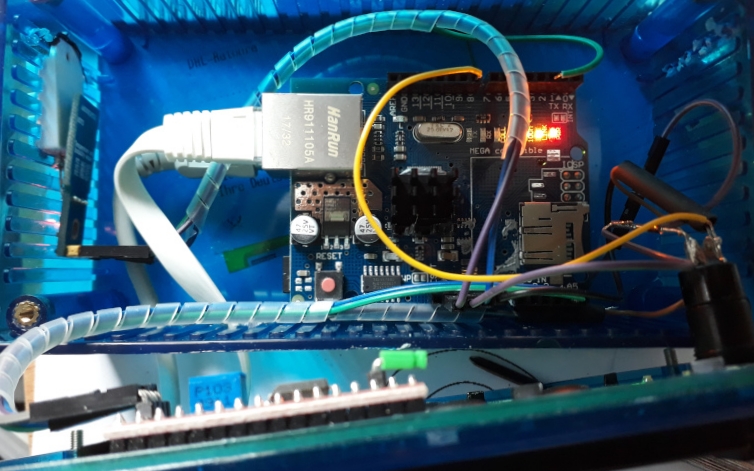
The ‘inside’ of his substitute of a room unit.
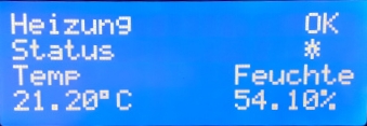
The display of his own built room unit.
A more detailed description including the circuit diagram and the software is available here in the German FHEM forum.
Also, he expanded the functionality and implemented push messaging for certain error cases. The description and the software can be found here in the German FHEM forum.
7.4.2 Room Temperature Sensor (Wemos D1 mini, DHT22, Display)
The member „Gizmo_the_great” of the FHEM forum has built a room temperature sensor based on a Wemos D1 mini and a DHT22 sensor. The current temperatures on the heating circuits 1 and 2 are additionally displayed at an OLED display. The Wemos D1 ist running ESPeasy.
A more detailed description of his project you can find in his GitHub Repo.
7.4.3 Substitute for a Room Unit with UDP Communication
7.4.3.1 UDP with Arduino UNO + LAN Shield
FHEM forum member “fabulous” has built a substitute for a room unit based on the above-mentioned variant of user “Andreas29”, which communicates with the BSB LAN adapter via UDP. An Arduino Uno including LAN shield, a 20x4 LCD and a push button are used. A detailed description and the corresponding code can be found here.
7.4.3.2 UDP with ESP32
BSB-LAN user “-cr “ has extended the above mentioned variant of user “fabulous” and adapted it to an ESP32 including ssd1306 display. His project BSBmonCR allows among other things a graphical display of selected parameters over time and a presence detection. In addition, it is even possible to do without a display, since the graphical representation can also be accessed via http and logging to a Dropbox account is also possible.
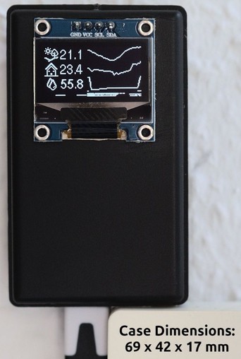
The finished setup including the case.
Graphical representation of three parameters over time.
The detailed description can be found in his GitHub repository.
7.4.4 Xiaomi Mijia BLE Sensors
| Attention |
|---|
| The following solution is not an ‘official’ version of BSB-LAN! Therefore it lacks certain functions and we can’t give any support for it! If questions arise, you can post them in this discussion thread though. |
| The possible integration of Xiaomi Mijia BLE sensors described in the following only works with ESP32 boards! |
User DukeSS developed the support for BLE (bluetooth low energy) sensors within a special version of BSB-LAN and offers it in his GitHub repository.
Many thanks!
If you are using an ESP32 board, you can use an alternative branch which offers support for BLE sensors.
With this, you can use different BLE sensors, here you can see a list of the supported types.
This solution has been tested with Xiaomi Mijia BLE sensors of the type LYWSD03MMC.
At this point only unencrypted messages are supported, so you have to use an alternative firmware for the sensors. For the mentioned Xiaomi Mijia BLE sensors of the type LYWSD03MMC you can find it here.
The limitations within this solution right now are e.g. that the OTA functionality won’t work, because the BLE implementation takes too much memory.
To use that function, you have to adjust two settings within the configuration of that special BSB-LAN version:
- Activate
EnableBLEto enable the BLE scan. - Add the MAC addresses of the desired BLE sensors within
BLE_sensors_macs.
Devices which aren’t listed here will be ignored. The order in this listing affects the order in the category of the output.
At the moment you can add up to 40 sensors (parameter numbers: NN20900-20199).
A listing of all BT devices found can be displayed through the URL command/CO(ifEnableBLEis activated).
7.5 LAN Options for the BSB-LPB-LAN Adapter
Even though the wired LAN connection is definitely the best option for integrating BSB-LAN into your network, it could be necessary to create an alternative way of connection, because a full-range wired connection (bus cable or LAN cable) just isn’t possible.
7.5.1 Usage of a PowerLAN / dLAN
The use of powerline adapters for expanding the LAN is an option, which could be the best and most reliable solution.
However, sometimes powerline installations can cause trouble because of possible interferences they may cause. If you have separated phases within your electrical installation, it may just not work though. In that case ask an electrician about a phase coupler that he may could install.
7.5.2 WLAN: Usage of an Additional Router
Another option is to connect the Arduino Due’s ethernet shield via LAN with an old WLAN router (e.g. an old FritzBox) and integrate the router in your network via WLAN as a client. The speed of transmission usually is fast enough for the use of BSB-LAN. If the WLAN signal is weak, you can probably try to change the antennas and mount bigger ones.
In addition to the use of a ‘normal’ router, there are small devices on the market that offer a RJ45 jack and a WLAN client or a WLAN client bridge mode. These devices connect to the network via WLAN (like the FritzBox solution described above). The Arduino can be connected via LAN cable to the device. These kinds of devices are often very small and can be plugged in a power outlet, so that the installation of the hardware can usually be done quite easily.
However, a stable and reliable WLAN connection should be achieved. Especially, if you are using additional smart home software to create logfiles, if you are using additional hardware like thermostats or if you want to control and influence the behaviour of your heating system.
