10. Excursus: Heating Controllers and Accessories
In general BSB-LAN works with controllers built by SIEMENS which are supported with a BSB and/or a LPB. These controllers are branded and used by different manufacturers of heating systems (e.g. Broetje, Elco). Please read the manual of your heating system to find out if the controller offers a BSB and/or LPB.
Clarification:
Whenever I’m talking about the “controller”, I mean the so called “BMU” (boiler management unit). That’s the device with all the electronics inside, which controls the whole function of the heating system and which is located inside the housing of the heating system. At this device the sensors, pumps and the operating and room units are connected to.
The ‘operating unit’ and the optional room units are the devices located outside at the housing of the heating system, the ones with a display and some buttons to interact with the BMU/controller.
Note:
Some recent models of Broetje don’t have a BSB and are NOT compatible with BSB-LAN. Please see chapter 10.2.3 for further informations.
10.1 Bus Systems of the Heating Controllers: BSB, LPB, PPS
BSB (Boiler System Bus), LPB (Local Process Bus) and PPS (point to point connection) are different types of bus systems (well, PPS isn’t really a bus though). They aren’t compatible between each other, so e.g. you can’t connect a BSB unit to a LPB.
Every of the controllers mentioned in this manual which are versions of RVS and LMS (and LMU7x) have at least one BSB port to offer. LPB isn’t available at each type of these controllers, but for the usage of BSB-LAN it’s not necessary - just use the BSB.
PPS isn’t used anymore at younger controllers, mostly old ones like RVA, RVP or LMU5x/6x are based on this type of connection system.
In the following subchapters I’ll give a short overview of the main aspects and differences of these bus/connection systems.
BSB (Boiler System Bus) and LPB (Local Process Bus) are two different bus types, which can be divided into two different usage purposes:
-
The BSB is a ‘local’ bus, where e.g. parts like the operating unit or a room unit are connected to the controller of the heating system. It offers ‘local’ access to the controller.
-
The LPB is a bus, which offers access across connected controllers (if the installation was set up right!). Using the LPB you could e.g. connect two or more heating units to realize a burner cascade or to connect the controller of you heating system with the controller of your solarthermic system.
If you have an existing installtion like that you could connect the BSB-LPB-LAN adapter to one of the mentioned controllers and would have access to certain parameters of both controllers. in that case you would have to pay attention to use the correct bus address of the units to make sure you reach the desired controller.
Even though it’s possible to use one adapter in an existing LPB structure with different controllers and query each controller by its own address, it’s advisable to use one adapter-setup (microcontroller + adapter) for each controller if they also offer a BSB port. It’s just more comfortable because you wouldn’t have to change the destination address every time you want to query another controller.
10.1.1 BSB
The BSB (Boiler System Bus) is basically a ‘local’ bus. By ‘local’ in this case, I mean the specific controller that is used in the heat generator.
The control panel, room units and expansion modules, for example, are connected to the BOD. These devices then have ‘local’ access to the controller. If the BSB-LAN setup is connected to the BSB, all bus devices of this controller can be accessed due to the unique addressing.
The BSB is available at the following presented controllers of the TYps RVS, LMS1x as well as LMU7x. If your controller has a BSB and an LPB connection and no other controller via LPB (e.g. another heat generator in a cascade connection, a solar system controller or similar) and you only want access to this one controller, then the connection of the BSB-LAN setup to the BSB connection is recommended.
Addressing Because of the bus structure, each participant gets a specific address. The following addresses are already defined:
| bus address | device address | device (name in the serial monitor) |
|---|---|---|
| 0x00 | 0 | controller itself („HEIZ“) |
| 0x03 | 3 | expansion module 1 („EM1“) / mixer-ClipIn AGU |
| 0x04 | 4 | expansion module 2 („EM2“) / mixer-ClipIn AGU |
| 0x06 | 6 | room unit 1 („RGT1: QAA55, QAA75, IDA“) |
| 0x07 | 7 | room unit 2 („RGT2: QAA55, QAA75“) |
| 0x08 | 8 | room unit 3/P and/or OCI700 servicetool („RGT3“) |
| 0x0A | 10 | operating unit (with display) 1 („DSP1“) |
| 0x0B | 11 | service unit (QAA75 defined as service unit) („SRVC“) |
| 0x0C | 12 | operating unit (with display) 2 („DSP2“) |
| 0x0D | 13 | operating unit (with display) 3 („DSP3“) |
| 0x31 | 49 | OZW672 webserver |
| 0x32 | 50 | (presumably) wireless receiver („FUNK“) |
| 0x36 | 54 | Remocon Net B („REMO”) |
| 0x42 | 66 | BSB-LPB-LAN adapter („LAN“) |
| 0x7F | 127 | broadcast message („INF“) |
Note:
The preset bus address 0x42 of the BSB-LPB-LAN adapter is the BSB device address 66. This address is set in the file BSB_LAN_config.h.
10.1.2 LPB
The LPB (Local Process Bus) is an ‘overlapping’ bus for the use of several connected controllers in a communication-capable network.
Via the LPB, several controllers can be connected to each other and (if the parameters are set correctly) they can share certain values or influence each other (like sending a telegram for starting the burner).
In this way, for example, a cascade circuit of several burners can be realized or a gas or oil heating system can be ‘connected’ (in terms of control technology) with a solar system or a solid fuel boiler.
The correct installation and connection of the individual components and the correct set up of the respective controllers should normally already be done by the installer of the heating system.
A comprehensive query of values or parameters of two or more controllers in the LPB network via the BSB-LAN setup can be done by adding the specific address of the bus participant.
The specific technical data, performance characteristics and requirements for corresponding installations and parameterizations with regard to the
device and segment addresses can be found in the respective technical documentation of the manufacturers.
Since the installation, which can be quite complex, is usually already carried out by the respective installer during installation, no further special features are discussed here.
For the interested user, two documents from “Siemens Building Technologies - Landis & Staefa Division” are recommended:
- CE1N2030D Local Process Bus LPB System Basics
- CE1N2032D Local Process Bus LPB project planning basics
Addressing
The addressing within the LPB is different than the one within the BSB. Basically there are two ‘addresses’: an address of a segment and an address of a unit. Both have different meanings. Because the topic LPB is pretty complex, please search for further informations by yourself. Especially the documents about the LPB of “Siemens Building Technologies - Landis & Staefa Division” should be regarded as they are the main sources for these informations.
Note:
The preset bus address 0x42 of the BSB-LPB-LAN adapter is the LPB segment address 4 with device address 3. This address is set in the file BSB_LAN_config.h. Usually it can be left to the default setting and doesn’t need to be changed.
10.1.3 PPS
Right now, the PPS will just be mentioned really short here, because it’s only available at old controllers and therefore not relevant for most of the users. As already said, PPS is not a real bus. It’s more a point-to-point communication protocol for the usage of connecting a room unit to a controller for example. So if you have an old heating system like a Broetje WGB 2N.x and you have (or can connect) a room unit like a QAA50 or QAA70, then you are using PPS.
The adapter has to be connected the same way the room unit would have to be. Please read the manual of your heating system to find out about that. In most cases though the two pins of the connectors at the controller are labeled as “A6” and “MD” (or just “M”). In that case, you have to connect “A6” to “CL+” and “MD”/”M” to “CL-“ of the adapter.
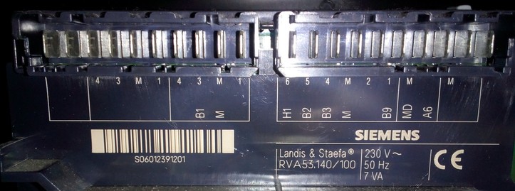
Connectors “A6” and “MD” at a Siemens RVA53 controller.
The functionality of this ‘bus’ is very limited, so you probably only have a dozen of parameters available. In the webinterface of BSB-LAN you only have access to the category “PPS-Bus”.
Note:
If there’s already a room unit like QAA70 connected to the controller, BSB-LAN only can read values. If you want BSB-LAN to be able to set certain values, you would have to disconnect the room unit for the time you want to have the BSB-LAN adapter connected!
Please take notice of the comments at the specific PPS definements in the file BSB_LAN_config.h when using PPS!
Important note for users of the old (retired) setup adapter v2 + Arduino Mega 2560:
Because of the time-critical communication of the PPS, it is recommended to adjust the setup for using the hardware serial. Therefore the following adaptions have to be done:
- The adapter has to be fully assembled.
- Only the solder jumer SJ1 has to be set.
- The adapter has to be plugged in one pinrow towards the center of the the arduino.
- The configuration has to be changed: set the pins within the variable “BSBbus” to 19 (RX) and 18 (TX) (instead of “68,69”).
10.2 Detailed Description of the Supported Controllers
The following list of controllers and descriptions should give a short overview of a selection of devices already supported by BSB-LAN and their rudimentary differences. The different controller-specific availability of special parameters will not further received. It should be noted, however, that via BSB-LAN several parameters are available which aren’t available by the regular operating unit of the heating system itself.
The entire range of functions of the respective controller types is generally available via BSB-LAN. However, this is naturally different with regard to the available parameters: A controller of the latest generation has more parameters and setting options than a controller of the oldest generation. However, this does not necessarily make the heating system more inefficient or make it ‘outdated’ and unusable per se! By using BSB-LAN, even the oldest supported controller usually can be made a little ‘smarter’ and integrated into the home automation system though.
| Note |
|---|
| In the following, the basic controller series such as LMU, LMS, RVS are roughly introduced. This is only intended to provide a basic understanding and overview of the different controller series. As a further subdivision, the two digits after the letter combination are usually also used, e.g. “RVS43.xxx”. However, in order to keep the scope of this chapter manageable, a further, more detailed subdivision of the respective controller series with the complete controller designation, e.g. “RVS43.222/xyz” or “RVS43.325/xyz” and their specific differences to each other will be omitted as far as possible. If more detailed, controller-specific information on the respective controller type is required, the relevant instructions of the heating manufacturer should be consulted. If these are not available or not comprehensive enough, it is recommended to search for the manuals of the controller manufacturer “Siemens Albatros” by specifying the complete controller identification. |
10.2.1 LMx Controllers
The following subchapters are about the LMU and LMS controller types. These seem to be used within gas fired heating systems.
10.2.1.1 LMU Controllers
Controllers of the series LMU54/LMU64 are installed in older systems, they are out of date. These controllers are based upon the OpenTherm protocol which is incompatible with the BSB-LAN project - they do not have BSB/LPB/PPS. This type of controller can be retrofitted with LPB by means of a ClipIn module (OCI420) though.
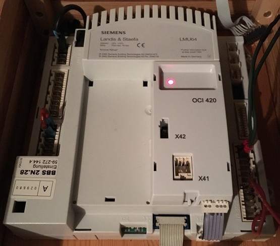
An LMU64 controller with an installed OCI420 ClipIn module.
Using BSB-LAN with these controller models is, according to experience, only possible to a limited extent. More detailed information can be found in chapter 10.2.4.
For retrofitting LPB with a ClipIn module (OCI420), please see chapter 10.2.6.
Controllers of the series LMU74/LMU75 appear to be the successors of the LMU54/LMU64 controller series and are also no longer installed.
An LMU7x controller.
The LMU7x controller type usually just offers BSB connection. If needed, LPB needs to be retrofitted using a ClipIn module (OCI420) (this is not necessary for using BSB-LAN though!).
The control unit usually is a variant of the Siemens AVS37.294 (so called “ISR Plus” whithin Broetje).
Usually NTC10k (QAD36, QAZ36) and NTC1k (QAC34 = outdoor temperature sensor) are used as sensors.
10.2.1.2 LMS Controllers
Controllers of the series LMS seem to be the successors of the LMU series and thus the current controller generation.
The (functional) difference between the LMS14 and the LMS15 seems to be the “Sitherm Pro” application to optimize the overall combustion process, which apparently only the LMS15 controller seems to offer.
The LMS controller type usually just offers a BSB connection. If needed, LPB can be retrofitted using a ClipIn module (OCI345) (this is not necessary for using BSB-LAN though!).
An LMS15 controller.
The operating unit usually is a variant of the Siemens AVS37.294 (so called “ISR Plus” whithin Broetje).
Usually NTC10k (QAD36, QAZ36) and NTC1k (QAC34 = outdoor temperature sensor) are used as sensors.
10.2.2 RVx Controllers
The following subchapters are about the RVA, RVP and RVS (current one) controller types. These seem to be used within oil fired heating systems, heat pumps and different ‘standalone’ systems (like solar or zone controllers).
10.2.2.1 RVA and RVP Controllers
Controllers of the type RVA seem to belong to the previous controller generation and, depending on the model, only offer a PPS (RVA53) or a PPS and a LPB connection (RVA63) but no BSB.
As an (included) operating unit usually a variant of the so called “Eurocontrol” (Broetje) is installed.
An RVA53 controller.
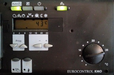
Frontside view: Operating unit of a RVA53 controller.
Controllers of the type RVP seem to be even older than RVA controllers and only offer a PPS interface.
10.2.2.2 RVS Controllers
Controllers of the type RVS seem to be the current controller generation.
They usually offer both a LPB and several BSB connections.
Exceptions seem to be the controllers of the series RVS21, RVS41, RVS51, RVS61 and RVS23:
- RVSx1 controllers are used within heat pumps, the RVS21 seems to offer only a BSB connector.
- RVS23 controllers are used on a particular Weishaupt model (WTU) and seem to only offer a LPB. These controllers seem to be labeled by Weishaupt as “WRS-CPU Bx”. Further information on this controller model can be found in [chapter 3.5] (chap03.md#35-special-case-weishaupt-heating-systems).
The operating unit usually is a variant of the Siemens AVS37.294 (so called “ISR Plus” whithin Broetje).
Usually NTC10k (QAD36, QAZ36) and NTC1k (QAC34 = outdoor temperature sensor) are used as sensors.
The following gives a short overview of the main RVS controller types.
RVS21.xxx
The RVS21 is the type of controller which is used in heatpumps. It offers BSB and a pair of connectors for an optional room unit.
An RVS21 controller.
If needed, LPB can be retrofitted using a ClipIn module (OCI345) (this is not necessary for using BSB-LAN though!).
RVS41.xxx
The RVS41 is another type of controller which is used within heat pumps. it offers BSB and LPB and seems to be pretty identical to the RVS43 (at least judging by the look of it).
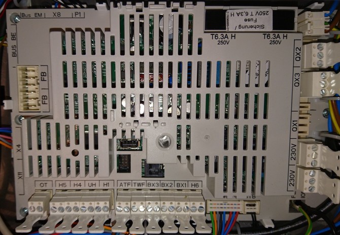
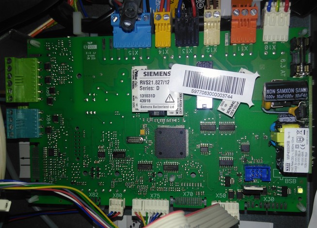
RVS43.xxx
The RVS43 is the series that is used, for example, in oil condensing boilers, the Broetje pellet boiler SPK, the Broetje cascade controller “ISR-BCA” and the Broetje heating system manager “ISR-HSM”; some manufacturers (e.g. Boesch) also use this controller type in heat pumps. However, depending on the respective heat generator or device (e.g. BCA, HSM), there are model-specific differences with regard to the connections and the scope of functions.
RVS43 series controllers are usually equipped with (at least) one BSB and one LPB connection.
The number of connectors and functions could be expanded with an AVS75 expansion module.
An RVS43.222 controller.
The model RVS43.325 is designated by Broetje as a replacement controller and can be used, among others, for oil condensing systems of the series BOB, SOB, WOB and the pellet heater SPK. In direct comparison to the RVS43.222 shown above from a Broetje SOB C for example, this controller has additional connections. In case that this controller type should be used as a replacement, it must be parameterized accordingly depending on the heating model. Further informations about this can be found within the specific replacement manual.
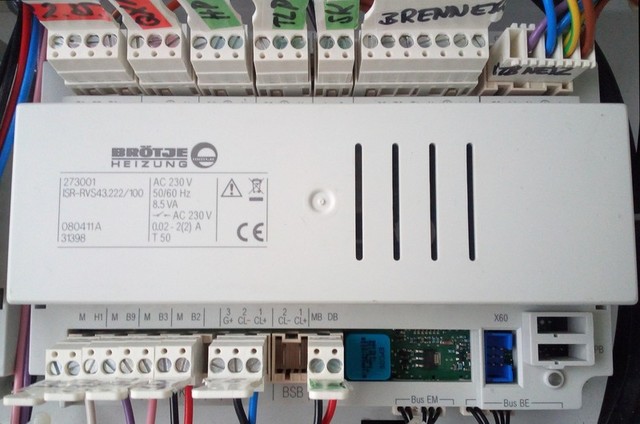
RVS46.xxx
The RVS46 is a small zone controller, which offers one (ZR1) or two (ZR2) connections for a pump/heating circuit. The RVS46 can control zones/circuits by it’s own, or integrated in the system via LPB connection to a main controller. It offers BSB and LPB.
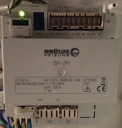
The ‘small’ zone controller ZR1.
The ZR1/2 is not designed for controlling the whole functionality of e.g. a complete oil fired burner.
RVS51.xxx
The RVS51 is the ‘bigger’ type of controller which is used in heatpumps. It offers BSB and LPB and seems to be pretty identical to the RVS63 (at least judging by the look of it).
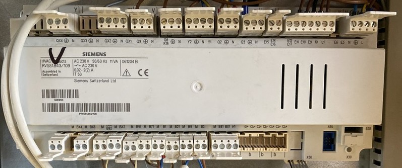
An RVS51.843 controller.
RVS61.xxx
The RVS61 is the ‘bigger’ type of controller which is used in heatpumps. It offers BSB and LPB and seems to be pretty identical to the RVS63 (at least judging by the look of it).
RVS63.xxx
The RVS63 seems to be the ‘biggest’ controller with the most connectors and functions. Basically he is designed to control systems which are more complex, e.g. additionally solar thermic systems or an integrated oven. Therefore it is named “Solar System Controller” within Broetje.
The RVS63 can already be built in within complex heating systems or it could optionally added. In that case it comes with an external housing and must be connected via LPB to the already existing controller. In that case, all the sensors, pumps etc. of the main system have to be connected to the RVS63, because it becomes the ‘main’ controller for the whole system.
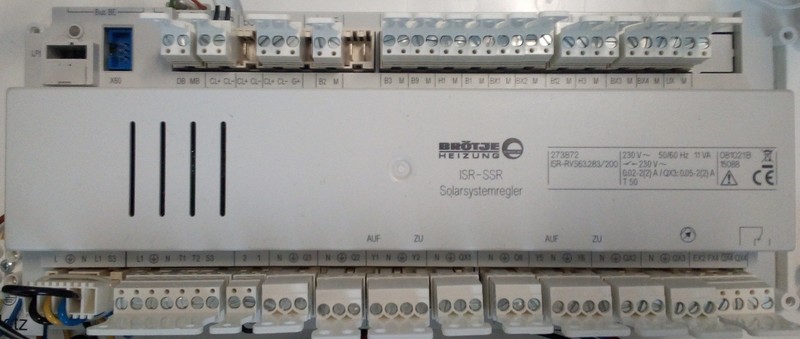
An RVS63 controller.
The RVS65.xxx seems to be pretty identical to the RVS63 and -until now- was reported only once by a user as being a wall-mounted “Solar System Controller” from Broetje.
10.2.3 Note: Incompatible Systems from Broetje and Elco
It should be noted that the heating manufacturers introduced new device models to the market. According to current knowledge this type of controller is NOT compatible with BSB-LAN.
Within Broetje these seem to be the heating system series
- WGB-K, WGB 14.1/22.1/28.1/38.1 (gas fired),
- WHC, WHS, WLC, WLS (gas fired),
- BOK (oil fired),
- BLW Split-P, BLW Split C and BLW Split-K C (heat pump).
Within Elco it seems to be the heating system series “Thision Mini”.
These systems seem to have ‘IWR CAN’-based controllers built in (at the heater unit “IWR Alpha”, room unit “IWR IDA”), which have neither a LPB nor a BSB.
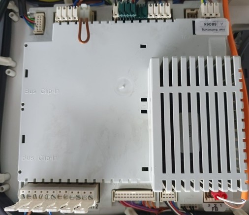
The following image of a WLC24 board shows the existing connections.
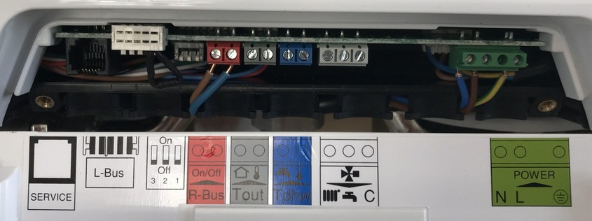
Connectors of the new controller model at a Broetje WLC24 - this controller is incompatible with BSB-LAN!
In addition to a service socket (probably IWR CAN) there are not further documented ‘L-Bus’ and ‘R-Bus’.
At the ‘R-bus’ (room unit bus) either a room thermostat (on / off) or the new ‘smart’
room unit “Broetje IDA” can be connected.
WATCH OUT:
At none of these connectors the BSB-LPB-LAN adapter can be connected!
10.2.4 Note: Special Case LMU54/LMU64 Controllers
LMU54 / LMU64 controllers are based on OpenTherm, which has different bus specifications and also a different communication protocol. Therefore, OpenTherm is not compatible with BSB-LAN.
However, often there is a possibility to connect this controller type anyway: as with the BSB controllers LMU7x and LMS1x, it is possible to retrofit a LPB by means of a so-called ClipIn module (OCI420). At this turn, the adapter can be connected.
An LMU64 controller with an installed OCI420 ClipIn module.
However, the functionality of this type of controller (even when using BSB-LAN) is relatively limited and also dependent to a certain extent on the software version of the controller (tested with LMU64, SW v2.08 vs. SW v3.0 vs SW v3.03): controllers with SW from v3.0 seem to offer more functions (controllable via BSB-LAN) than controllers with SW <v3.0. In particular, the two setpoint temperature parameters 709 and 711 should be mentioned here. On their basis the burner behavior could be determined to a certain extent - these can only be used or changed with SW from v3.0. (Note: There is still an attempt if the burner behavior can be satisfactorily influenced by relays on another contact, but up to now we didn’t find a solution for that.)
However, according to current knowledge, parameters such as outside temperature, boiler temperature, DHW temperature, flow temperature, etc. can be accessed within all mentioned software versions.
To be fair, it must be said here that the additional financial expense for purchasing an OCI420 LPB-ClipIn module may not be ‘worthwhile’. However, this depends on the pursued goal. If you only want to log temperatures to get a rough overview of the actual state of the heating system, a more reasonable solution with a corresponding DS18B20 temperature sensor installation would be sufficient. If you want to be able to e.g. query the error log of the controller, then you’ll need the additional OCI420+BSB-LAN setup.
However, it has to be said clearly again that ‘controlling’ of the beahviour of the burner is only possible in a very limited way (if it’s possible at all).
Hints for connection and configuration of an OCI420-ClipIn are given in chapter 10.2.6.
The following is an example of a complete query of an LMU64 with SW v3.03 (the ‘latest’ version with the most parameters available) - this gives you an impression of what can be retrieved via BSB-LAN at best.
1 Uhrzeit und Datum - Uhrzeit: 12:30:55
2 Uhrzeit und Datum - Tag/Monat: 24.01.
3 Uhrzeit und Datum - Jahr: 2022
70 Bedieneinheit - Geräte-Version Bedienteil: 30.3
701 Heizkreis 1 - Präsenztaste (temporäre Abwesenheit):	---
709 Heizkreis 1 - Komfortsollwert Minimum: 10.0 °C
711 Heizkreis 1 - Komfortsollwert Maximum: 30.0 °C
720 Heizkreis 1 - Kennlinie Steilheit: 18
721 Heizkreis 1 - Kennlinie Verschiebung: 0.0 °C
730 Heizkreis 1 - Sommer-/ Winterheizgrenze: 21 °C
734 Heizkreis 1 - Raumsollabsenkung mit Schaltuhr: 10.0 °C
781 Heizkreis 1 - Schnellabsenkung Faktor: 4
850 Heizkreis 1 - Estrichfunktion: 0 - Aus
884 Heizkreis 1 - Drehzahlstufe Auslegungspunkt: 17
885 Heizkreis 1 - Pumpe-PWM Minimum: 41 %
886 Heizkreis 1 - Norm Außentemperatur: -20 °C
887 Heizkreis 1 - Vorlaufsoll Norm Außentemperatur: 72.0 °C
888 Heizkreis 1 - dt Überhöhungsfaktor: 25.0 %
889 Heizkreis 1 - Filterzeitkonstant Drehzahlregler: 99 %
891 Heizkreis 1 - dT Vorhaltezeit Tv: 0 s
892 Heizkreis 1 - dT Nachstellzeit Tv: 50 s
893 Heizkreis 1 - dT Abtastfaktor: 10
894 Heizkreis 1 - dT Spreizung Norm Außentemperatur: 20.0 °C
895 Heizkreis 1 - dT Spreizung Maximum: 20.0 °C
1001 Heizkreis 2 - Präsenztaste (temporäre Abwesenheit): ---
1020 Heizkreis 2 - Kennlinie Steilheit: 14
1021 Heizkreis 2 - Kennlinie Verschiebung: 0.0 °C
1130 Heizkreis 2 - Mischerüberhöhung: 10.0 °C
1134 Heizkreis 2 - Antrieb Laufzeit: 150 s
1150 Heizkreis 2 - Estrichfunktion: 0 - Aus
1301 Heizkreis 3/P - Präsenztaste (temporäre Abwesenheit: ---
1603 Trinkwasser - Manueller TWW-Push: Aus
1614 Trinkwasser - TWW Nennsollwert Maximum: 2.2 °C
1615 Trinkwasser - TWW Reduziertsollwert Minimum: 0.3 °C
2210 Kessel - Sollwert Minimum: 20.0 °C
2212 Kessel - Sollwert Maximum: °C 000084 - decoding error
2215 Kessel - Max. Regeldifferenz ohne Abbruch der Mindestpause (°K): 60.0 °C
2250 Kessel - Pumpennachlaufzeit: 10 min
2440 Kessel - Gebläse-PWM Hz Maximum: 70 %
2441 Kessel - Gebläsedrehzahl Hz Maximum: 5400 U/min
2442 Kessel - Gebläse-PWM Reglerverzögerung: 19 %
2443 Kessel - Gebläse-PWM Startwert DLH: 40 %
2444 Kessel - Leistung Minimum: 4.0 kW
2445 Kessel - Nennleistung Kessel: 15.0 kW
2451 Kessel - Brennerpausenzeit Minimum: 120 s
2452 Kessel - Schaltdifferenz Brennerpause: 30.0 °C
2453 Kessel - Reglerverzögerung Dauer: 60 s
2454 Kessel - Schaltdifferenz ein HK: 4.0 °C
2455 Kessel - Schaltdifferenz aus Min HK: 5.0 °C
2456 Kessel - Schaltdifferenz aus Max HK: 7.0 °C
2458 Kessel - Einschwingzeit TWW Max: 3 min
2459 Kessel - Sperrzeit dynamische Schaltdifferenz: 0 s
2471 Kessel - Pumpennachlaufzeit HK: 10 min
2472 Kessel - Pumpennachlauftemperatur TWW: 72.0 °C
2473 Kessel - Abgastemperatur Leistungsreduktion: 80 °C
2521 Kessel - Frostschutz Einschalttemperatur: 5.0 °C
2522 Kessel - Frostschutz Ausschalttemperatur: 10.0 °C
2547 Kessel - Abtastintervall DLH: 0.2 s
2730 Sitherm Pro - Ionisationsstrom: 131.80 µA
2792 Wärmepumpe - Pumpendrehzahl Minimum: 41 %
3810 Solar - Temperaturdifferenz ein: 8.0 °C
3811 Solar - Temperaturdifferenz aus: 4.0 °C
3812 Solar - Ladetemperatur Min TWW-Speicher: 30.0 °C
3831 Solar - Mindestlaufzeit Kollektorpumpe: 60 s
3840 Solar - Kollektortemperatur Frostschutz: 0.0 °C
3850 Solar - Kollektorüberhitzschutz: 120.0 °C
5019 Trinkwasserspeicher - TWW Nachladeüberhöhung Schichtenspeicher: 5.0 °C
5020 Trinkwasserspeicher - TWW Vorlaufsollwertüberhöhung: 18.0 °C
5050 Trinkwasserspeicher - TWW Ladetemperatur Maximum: 80.0 °C
5055 Trinkwasserspeicher - TWW Rückkühltemperatur: 80.0 °C
5100 Trinkwasserspeicher - TWW Pumpe-PWM Durchladung: 18 %
5126 Trinkwasserspeicher - Mischer Nachstellzeit Tn: 100 s
5400 Trinkwasser Durchlauferhitzer - Komfortsollwert: 45.0 °C
5420 Trinkwasser Durchlauferhitzer - Vorlauf-Sollwertüberhöhung: °C 0024 - decoding error
5430 Trinkwasser Durchlauferhitzer - Einschaltdifferenz im BW-Betrieb (Fühler 1): 4.0 °C
5431 Trinkwasser Durchlauferhitzer - Min. Ausschaltdifferenz im BW-Betrieb (Fühler 1): 2.0 °C
5450 Trinkwasser Durchlauferhitzer - Schwelle zum Beenden einer BW-Zapfung bei DLH: 0.20313 K/s
5451 Trinkwasser Durchlauferhitzer - Schwelle für Bw-Zapfung bei DLH in Komfort: -0.20313 K/s
5452 Trinkwasser Durchlauferhitzer - Schwelle für Bw-Zapfung bei Dlh in Heizbetrieb: -0.29688 K/s
5453 Trinkwasser Durchlauferhitzer - Sollwertkorrektur bei Komfortregelung mit 40°C (°K): 0.0 °C
5454 Trinkwasser Durchlauferhitzer - Sollwertkorrektur bei Komfortregelung mit 60°C (°K): 0.0 °C
5455 Trinkwasser Durchlauferhitzer - Sollwertkorrektur bei Auslaufregelung mit 40°C (°K): 0.0 °C
5456 Trinkwasser Durchlauferhitzer - Sollwertkorrektur bei Auslaufregelung mit 60°C (°K): 0.0 °C
5480 Trinkwasser Durchlauferhitzer - Komfortzeit ohne Hz-Anforderung: min 000000 - unknown type
5481 Trinkwasser Durchlauferhitzer - Komfortzeit mit Hz-Anforderung: 0 min
5482 Trinkwasser Durchlauferhitzer - Zeit TWW-FlowSwitch geschlossen: 0 s
5483 Trinkwasser Durchlauferhitzer - Zeit TWW-Komfort FlowSwitch geschlossen: 0 s
5486 Trinkwasser Durchlauferhitzer - Reglerverzögerung bei Takten in DLH Auslaufbetrieb: 0 s
5487 Trinkwasser Durchlauferhitzer - Pumpennachlauf Komfort in Minuten: 255 min
5488 Trinkwasser Durchlauferhitzer - Pumpennachlauf Komfort in Sekunden: s 0000000000 - decoding error
5701 Konfiguration - Hydraulisches Schema: 58
5732 Konfiguration - TWW Pumpenpause Umsch UV: 4 s
5733 Konfiguration - TWW Pumpenpause Verzögerung: 1 s
5761 Konfiguration - Zubringerpumpe Q8 Bit 0-3: 00000000	Zonen mit ZubringerpumpeHK1 mit ZubringerpumpeHK2 mit ZubringerpumpeTWW mit Zubringerpumpe
5920 Konfiguration - Programmierbarer Ausgang K2: 0 - Default, Keine Funktion
5922 Konfiguration - Relaisausgang 1 RelCl: 0 - Default, Keine Funktion
5923 Konfiguration - Relaisausgang 2 RelCl: 0 - Default, Keine Funktion
5924 Konfiguration - Relaisausgang 3 RelCl: 0 - Default, Keine Funktion
5926 Konfiguration - Relaisausgang 1 SolCl: 0 - Default, Keine Funktion
5927 Konfiguration - Relaisausgang 2 SolCl: 0 - Default, Keine Funktion
5928 Konfiguration - Relaisausgang 3 SolCl: 0 - Default, Keine Funktion
5950 Konfiguration - Funktion Eingang H1: 0 - Default
5973 Konfiguration - Funktion Eingang RelCl: 0 - Keine Funktion
5975 Konfiguration - Externer Vorlaufsollwert Maximum: 100.0 °C
5976 Konfiguration - Externe Leistungsvorgabe Schwelle: 5 %
5978 Konfiguration - Funktion Eingang SolCl: 0 - kein
6089 Konfiguration - Mod Pumpe Drehzahlstufen: 30
6092 Konfiguration - Mod Pumpe PWM: 3 %
6093 Konfiguration - Mod Pumpe PWM Max: 85 %
6127 Konfiguration - Pumpen/Ventilkick Dauer: 5 s
6140 Konfiguration - Wasserdruck Maximum: 2.5 bar
6141 Konfiguration - Wasserdruck Minimum: 0.7 bar
6143 Konfiguration - Wasserdruckschwelle für Kessel und Pumpe aus: 0.5 bar
6144 Konfiguration - Schaltdifferenz Wasserdruck: 0.3 bar
6146 Konfiguration - Druckwert 3.5V: 0.0 bar
6220 Konfiguration - Software-Version: 30.3
6222 Konfiguration - Gerätebetriebsstunden: 19042 h
6223 Konfiguration - Bisher unbekannte Geräteabfrage: 003A - decoding error
6224 Konfiguration - Geräte-Identifikation: LMU54/64
6225 Konfiguration - Gerätefamilie: 64
6226 Konfiguration - Gerätevariante: 100
6227 Konfiguration - Objektverzeichnis-Version: 202.0
6229 Konfiguration - EEPROM-Version: 15.0
6230 Konfiguration - KonfigRg0 Bit 0-7: 00100011	Fühlerunterbruch Rücklauffühler unterdrückenFühlerunterbruch Rücklauffühler ausgebenFühlerunterbruch Trinkwasserfühler unterdrückenFühlerunterbruch Trinkwasserfühler ausgebenFühlerunterbruch Abgastemperaturfühler unterdrückenFühlerunterbruch Abgastemperaturfühler ausgebenFühlerunterbruch Außentemperaturfühler unterdrückenFühlerunterbruch Außentemperaturfühler ausgebenFühlerunterbruch Wasserdruckfühler unterdrückenFühlerunterbruch Wasserdruckfühler ausgebenFühlerunterbruch Vorlauffühler unterdrückenFühlerunterbruch Vorlauffühler ausgebenFühlerunterbruch Fühler am ClipIn unterdrückenFühlerunterbruch Fühler am ClipIn ausgeben
6240 Konfiguration - KonfigRg1 Bit 0-7: 00110100	Vorrang Trinkwasser: absolutVorrang Trinkwasser: gleitendVorrang Trinkwasser: keinKlemmenbelegung X10-02: RTKlemmenbelegung X10-02: SchaltuhrKlemmenbelegung X10-01: RTKlemmenbelegung X10-01: SchaltuhrAnlagenfrostschutz ausAnlagenfrostschutz einWirkung Schaltuhr an X10-01: HeizkreisWirkung Schaltuhr an X10-01: TWWBetriebsart des Heizkreises bei Modemfunktion: StandbyBetriebsart des Heizkreises bei Modemfunktion: Reduziert
6250 Konfiguration - KonfigRg2 Bit 0-7: 10000000	Pumpennachlauf TWW in den HeizkreisPumpennachlauf TWW in den TWW-WärmetauscherKomforttemperaturniveau wie AuslauftemperaturKomforttemperaturniveau wie BereitschaftstemperaturKomfort PID Regelungsfühler: KesselvorlaufKomfort PID Regelungsfühler: TWW-FühlerKomfort PID Regelungsfühler: KesselrücklaufFühleranordnung Schichtenspeicher SSP: KVFFühleranordnung Schichtenspeicher SSP: KRF, nicht bei SSPFühleranordnung Schichtenspeicher SSP: KRF, nur SSP
6270 Konfiguration - KonfigRg4 Bit 0-7: 01000000	Zubringerfunktion Q8: ausZubringerfunktion Q8: einGebäudebauweise: leichtGebäudebauweise: schwerAnschlussklemme TW-Thermostat: Fühler an X10/TWFAnschlussklemme TW-Thermostat: Thermostat an X10/TWFKonfiguration 3-Wege-Ventil: keinKonfiguration 3-Wege-Ventil: MagnetventilKonfiguration 3-Wege-Ventil: MotorventilKonfiguration 3-Wege-Ventil: Motorventil invers
6280 Konfiguration - KonfigRg5 Bit 0-7: 00000111	Wassermangelsicherung Strömungswächter->StörstellungWassermangelsicherung Strömungswächter->StartverhinderungWassermangelsicherung Wasserdruckwächter->StörstellungWassermangelsicherung Wasserdruckwächter->StartverhinderungWassermangelsicherung Drehzahlbegrenzung ausWassermangelsicherung Drehzahlbegrenzung einBits 3-7: Grundeinstellung; nicht verändern!
6290 Konfiguration - KonfigRg6 Bit 0-7: 11100000	Initialisierung ISR: Sofortige Übernahme der Stellgröße nach FreigabeInitialisierung ISR: Stoßfreier Übergang nach FreigabeVerriegelung Fremd-Room Units: ausVerriegelung Fremd-Room Units: einQuelle BW-Sollwert: RUQuelle BW-Sollwert: HMISperrsignalberechnung deaktiviertSperrsignalberechnung aktiviertSchnelle Wechsel der Drehzahlgrenzen: Normale AbarbeitungSchnelle Wechsel der Drehzahlgrenzen: BeschleunigtInitialisierung ISR: Nur bei BetriebsartwechselInitialisierung ISR: Immer bei BrennerstartPWM-Gebläserampen: ausPWM-Gebläserampen: ein
6300 Konfiguration - KonfigRg7 Bit 0-7: 00001111	Heizkreispumpe: stufigHeizkreispumpe: modulierendDelta-T-Begrenzung: ausDelta-T-Begrenzung: einDelta-T-Überwachung: ausDelta-T-Überwachung: einAnlagenvolumen: kleinAnlagenvolumen: mittelAnlagenvolumen: großDelta-T-Überwachung im Reduziert-Betrieb: ausDelta-T-Überwachung im Reduziert-Betrieb: einReglerverzögerung: nur im Heizbetrieb aktivReglerverzögerung: in allen Betriebsarten aktivPumpe Q1 Modulation in Systemen 51,54,55,67,70,71: ausPumpe Q1 Modulation in Systemen 51,54,55,67,70,71: ein
6310 Konfiguration - KonfigRg8 Bit 0-7: 00000000	Sekundärtauscher: PlattenwärmetauscherSekundärtauscher: Wendelwärmetauscher primärseitigSekundärtauscher: Wendelwärmetauscher sekundärseitig1. Maximum Durchlauferhitzer-Regelung: auswerten1. Maximum Durchlauferhitzer-Regelung: ignorierenDurchlauferhitzer Anfrage über DLH1 Sensor oder Flow-SwitchDurchlauferhitzer Anfrage nur über Flow-SwitchPosition von Verteilventil nach Durchlauferhitzer: LetztePosition von Verteilventil nach Durchlauferhitzer: Heizposition
6330 Konfiguration - KonfigRg10 Bit 0-7: 00000000	Kesselpumpe bei Brennersperre: keine AbschaltungKesselpumpe bei Brennersperre: AbschaltungBrennersperre nur bei HeizanforderungBrennersperre nur bei Heiz- und TWW-AnforderungDurchlauferhitzertaktschutz durch Temperaturerhöhung: ausDurchlauferhitzertaktschutz durch Temperaturerhöhung: einPosition des TWW-Speichers: vor hydraulischer WeichePosition des TWW-Speichers: nach hydraulischer WeicheZubringerpumpe bei Brennersperre: keine AbschaltungZubringerpumpe bei Brennersperre: AbschaltungGebläseabschaltung bei Heizanforderung: FreigabeGebläseabschaltung bei Heizanforderung: keine FreigabePumpennachlauf TWW bei weiteren Wärmeanforderungen: UnterdrückenPumpennachlauf TWW bei weiteren Wärmeanforderungen: Durchführen
6343 Konfiguration - Bisher unbekannte Geräteabfrage: 0001260096 - unknown type
6344 Konfiguration - Hersteller-ID (letzten vier Bytes): 1012140155
1012140155
6600 LPB-System - Geräteadresse: 00.01
6604 LPB-System - Busspeisung Funktion: 1 - Automatisch
6605 LPB-System - Busspeisung Status: 255 - Ein
6610 LPB-System - Anzeige Systemmeldungen: 255 - Ja
6625 LPB-System - Trinkwasserzuordnung: 0 - Lokale Heizkreise
6640 LPB-System - Uhrbetrieb: 2 - Slave mit Fernverstellung
6650 LPB-System - Außentemperatur Lieferant: 00.01
6699 LPB-System - Software Version Einschub: 0.7
6701 Fehler - Unknown command: 0000 - unknown type
6705 Fehler - SW Diagnosecode: 0 - not found
6800 Fehler - Historie 1: 5
6803 Fehler - Historie 1 Fehlermeldung: 153 - Entriegelungstaste wurde betätigt
6805 Fehler - SW Diagnosecode 1: 259
6806 Fehler - FA Phase 1: 0 - Standby
6810 Fehler - Historie 2: 4
6813 Fehler - Historie 2: 133 - Keine Flammenbildung nach Ablauf der Sicherheitszeit
6815 Fehler - SW Diagnosecode 2: 102 - Uhrzeitmaster ohne Gangreserve (LPB)
6816 Fehler - FA Phase 2: 14 - not found
6820 Fehler - Historie 3: 0
6823 Fehler - Historie 3 Fehlermeldung: 0 - kein Fehler
6825 Fehler - SW Diagnosecode 3: 0 - not found
6826 Fehler - FA Phase 3: 0 - Standby
6830 Fehler - Historie 4: 0
6833 Fehler - Historie 4 Fehlermeldung: 0 - kein Fehler
6835 Fehler - SW Diagnosecode 4: 0 - not found
6836 Fehler - FA Phase 4: 0 - Standby
6840 Fehler - Historie 5: 0
6843 Fehler - Historie 5 Fehlermeldung: 0 - kein Fehler
6845 Fehler - SW Diagnosecode 5: 0 - not found
6846 Fehler - FA Phase 5: 0 - Standby
7001 Wartung/Sonderbetrieb - Meldung: 0
7010 Wartung/Sonderbetrieb - Quittierung Meldung: 1 - Ein
7011 Wartung/Sonderbetrieb - Repetitionszeit Meldung: 14 Tage
7040 Wartung/Sonderbetrieb - Repetitionszeit Meldung: h 0001499700 - decoding error
7041 Wartung/Sonderbetrieb - Brennerstunden seit Wartung: h 0002255100 - decoding error
7042 Wartung/Sonderbetrieb - Brennerstarts Intervall: 0
7043 Wartung/Sonderbetrieb - Brennerstarts seit Wartung: 400
7044 Wartung/Sonderbetrieb - Wartungsintervall: 6000 h
7045 Wartung/Sonderbetrieb - Zeit seit Wartung: 0 Monate
7050 Wartung/Sonderbetrieb - Gebläsedrehzahl Ion Strom: 4000 U/min
7051 Wartung/Sonderbetrieb - Meldung Ion Strom: 0
7700 Ein-/Ausgangstest - Relaistest: 0 - Kein Test
8310 Diagnose Erzeuger - Kesseltemperatur: 76.0 °C
8311 Diagnose Erzeuger - Kesselsollwert: 2.3 °C
8314 Diagnose Erzeuger - Kesselrücklauftemperatur Ist: 57.5 °C
8321 Diagnose Erzeuger - Aktuelle Regeldifferenz: 4.4 °C
8324 Diagnose Erzeuger - Brennergebläsesollwert: 0 U/min
8325 Diagnose Erzeuger - PWM Drehzahlregler (Proz): 0 %
8326 Diagnose Erzeuger - Brennermodulation: 0 %
8329 Diagnose Erzeuger - Ionisationsstrom: 0.00 µA
8336 Diagnose Erzeuger - Betriebsstunden Brenner: 19042 h
8337 Diagnose Erzeuger - Startzähler Brenner: 3467
8338 Diagnose Erzeuger - Betriebsstunden Heizbetrieb: 57508 h
8339 Diagnose Erzeuger - Betriebsstunden TWW: 2680 h
8340 Diagnose Erzeuger - Betriebsstunden externe Wärmeanforderung: 0 h
8530 Diagnose Erzeuger - Betriebsstunden Solarertrag: 0 h
8700 Diagnose Verbraucher - Außentemperatur: 6.5 °C
8705 Diagnose Verbraucher - Außentemperatur LPB: --- °C
8741 Diagnose Verbraucher - Raumsollwert 1: 30.0 °C
8750 Diagnose Verbraucher - Mod Pumpe Sollwert: 60 %
8773 Diagnose Verbraucher - Vorlauftemperatur 2: 36.0 °C
8830 Diagnose Verbraucher - Trinkwassertemperatur 1: --- °C
8831 Diagnose Verbraucher - Trinkwassersollwert: 55.0 °C
8832 Diagnose Verbraucher - Trinkwassertemperatur 2: 52.0 °C
8950 Diagnose Verbraucher - Schienenvorlauftemperatur: 77.5 °C
8952 Diagnose Verbraucher - Schienenrücklauftemperatur: 58.0 °C
9500 Feuerungsautomat - Vorlüftzeit: 3.0 s
9502 Feuerungsautomat - Gebläseansteuerung Vorlüftung: 40 %
9504 Feuerungsautomat - Solldrehzahl Vorlüftung: 3500 U/min
9510 Feuerungsautomat - Gebläseansteuerung Zündung: 40 %
9512 Feuerungsautomat - Solldrehzahl Zündung: 3500 U/min
9520 Feuerungsautomat - Gebläseansteuerung Betrieb. Min: 14 %
9522 Feuerungsautomat - Gebläseansteuerung Betrieb. Max: 70 %
9524 Feuerungsautomat - Solldrehzahl Betrieb Min: 1450 U/min
9527 Feuerungsautomat - Solldrehzahl Betrieb Max: 5400 U/min
9540 Feuerungsautomat - Nachlüftzeit: 2.0 s
9560 Feuerungsautomat - Gebläseansteuerung Durchladung: 24.0 %
9563 Feuerungsautomat - Solldrehzahl Durchladung: 3950 U/min
10.2.5 Note: Special Case Weishaupt Heating Systems
Some Weishaupt devices (see list of successfully tested devices: Weishaupt WTU with WRS-CPU control unit) have RVS23 controllers installed. This controller type has a LPB on which the existing installation of Weishaupt systems is already based: room units, operating units and extension modules are already connected to each other via LPB. The adapter can also be connected to this LPB, but it must be correctly integrated into the existing LPB installation. In general, this isn’t a problem with the default LPB address of the adapter (segment 4, device address 3), but it should be checked again if there are any communication problems.
The Weishaupt devices also seem to have a service socket in addition to the regular operating unit, with two of the four pins provided and led out. According to the statement of a Weishaupt user (Thanks to BSB-LAN user Philippe!), the upper one of the two pins seems to be MB and the lower one seems to be DB.
10.2.6 Note: Retrofitting an LPB by Using an OCI420 ClipIn
If an OCI420 should be connected and used with a LMU controller (LMU64/LMU7x), the installation and the connection must be made in accordance with the respective operating instructions.
There are, however, a few key points that usually can’t be found in the operating instructions although they are necessary for a successful operation. This mainly concerns the settings that have to be made for the LPB power supply. Furthermore, the LPB device address 1 with segment address 0 must be set and the setting as the time master has to be made.
As always, the following information comes without any guarantee!
If you follow the instructions on the OCI420, you will most likely encounter error 81, which means “short circuit in the LPB bus or no LPB bus power supply”. If the OCI420 has been connected correctly, the LPB bus power must be activated in this case. The parameter is “LPBKonfig0”.
The following settings are described for controllers of type LMU64. Except for the parameter numbers, the settings of the bits are identical for other LMx controllers.
For the LMU64, the relevant parameter has the number 604 (for LMU74: parameter number 6006). Here are eight bits (604.0 to 604.7) available to be set as follows (where “0” = OFF and “1” = ON):
604.0 = 0 → time master
604.1 = 1 → time master
604.2 = 1 → distributed bus supply AUTOMATIC
604.3 = 1 → status LPB bus supply: 1 = active
604.4 = 1 → event behavior allowed
604.5 = 0 → domestic hot water allocation
604.6 = 0 → domestic hot water allocation
604.7 = 0 → no priority of LMU request before external power specification
If you call up the ‘overview’ of the LPBKonfig0 settings, however, the bit order is displayed from back to front (from bit 7 to bit 0!) and should be as follows after the successful setting: 00011110.
Furthermore, the following settings have to be made:
605 LPB device address = 1
606 LPB segment address = 0
After successful setting, no error code should occur and the red LED on the OCI420 should flash at a regular interval.
If, on the other hand, error 82 is displayed, the LPB addresses must be checked, since in this case there is an LPB address collision (which, however, should not occur with the above settings and the default address of BSB-LAN).
10.3 Expansion- and ClipIn-Modules
If the available connectors and the range of function of the specific controller aren’t enough (e.g. retrofitting of a solarthermic system), one can expand the system by using an expansion- or ClipIn-module. An expansion module offers connectors for (e.g.) a pump circuit and the belonging sensors.
These modules are being connected at the main controller by using a special bus cable and the dedicated connector. Internally they are communicating with the controller via BSB (an exception seems to be the used controller type within the named Weishaupt heating systems). The parameterization takes places via the operating unit of the connected controller.
Therefore, access to an extension module is only possible via the specific parameters within the main controller. Because the expansion modules are listed within a query of ip/Q, I’ll present the two main types really short in the follwing.
Note:
If you want to retrofit an expansion module, of course see the specific manual of your heating system for further informations and call a heating engineer for the installation.
Expansion modules of the type AVS75.xxx are used within the RVS and LMS controller types. The bus connection usually takes places via the connector “Bus-EM”.
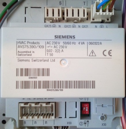
Expansion module AVS75.390.
Expansion modules for LMU controller types are named “ClipIn-module”. There seem to be different types for the specific needs (e.g. relay module, solar module). In general, the main appelation seems to be AGU2.5x (where the “x” seems to label the respective version), the bus connection usually takes place via the connector “X50”.
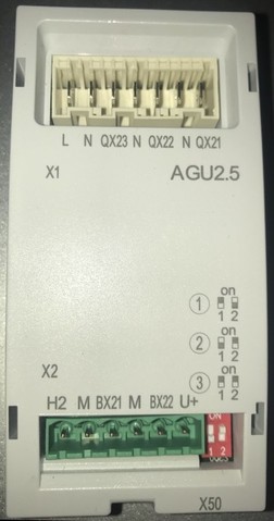
ClipIn-module AGU2.55.
10.4 Operating Units
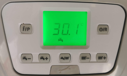
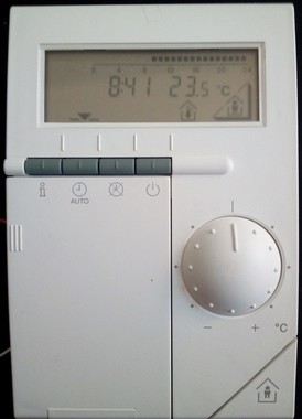
The operating unit (located at the heating system itself) within the systems of the recent years (with controller types LMU7x, LMS1x, RVS) usually are types of the AVS37.xxx. They look pretty much the same within the different manufacturers, within specific systems (e.g. heat pumps) certain buttons or functions can differ though.
If you compare the look of the AVS37 operating unit and the QAA75.61x room unit, you can see that they actually also look pretty identical and the usage of both devices is also almost the same. In most cases the heater sided operating unit constantly shows the temperature of the heating device and the room unit shows the room temperature. Both units spread these values regularly (approx. every 10 seconds) over the BSB as a broadcast (INF-message).
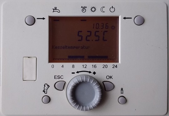
A typical operating unit AVS37.
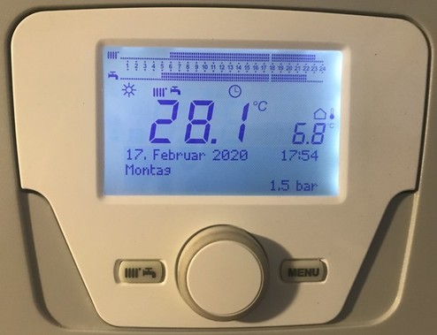
The successor to the AVS37 model is the AVS74.xxx. It is equipped with a 3.8” LCD display and a rotary/push knob with which all settings are made. It is also used as a room unit under the designation QAA74.
An AVS74 operating unit.
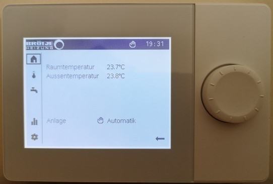
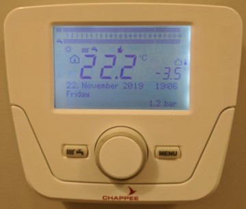
Recently some manufacturers are using a new type of operating unit though, it’s called QAA75.91x. It seems to be possible to detach these units from the heater itself and -by using an optional connection setup- to install them in your living area. In that case they are still working as the main operating unit for the controller, but with the additional benefits of a room unit.
A QAA75.91x operating unit.
In addition, there has recently been another model, the AVS77.xxx. This operation unit has so far only been reported to us from a user with a certain Baxi heating system (Baxi Luna Duo Tec MP). This unit offers (among other) buttons for changing the DHW and HC target temperature in small steps (degrees), but no longer has a rotary knob.
An AVS77.xxx operating unit.
| Note |
|---|
| It seems that changing the operating mode using the DHW/HC button (in the center of the operating unit) for certain modes has the consequence that changing it via BSB-LAN and the ‘regular’ parameters 1600 (DHW) and 7xx (HC) is no longer possible if an operating mode other than “both” has been selected by using the mentioned key. The function of this new key is not (yet) implemented in BSB-LAN. If a change of the operating modes via BSB-LAN is desired, it must be ensured that the operating mode is set to “both” by using the mentioned key. |
10.5 Conventional Room Units for the Listed Controllers
The following briefly describes the different room units. These are also manufactured by SIEMENS and branded by the different heating manufacturers. Thus, they can be used across manufacturers, e.g. a corresponding QAA room unit of Elco can be used on a Broetje heater (of course, always provided that it is the right type of room unit). It’s not yet known if there are certain restrictions in individual cases.
As optional ‘local’ accessory parts of the heating system, they are connected to the BSB. That’s why the connector for room units is what you are looking for, when you want to connect the adapter. So if you connect a room unit and adjusted the settings of the specific parameters (e.g. usage and influence of the room unit and room temperature), you can directly access the measured room temp. If you don’t have an external room unit, but you can or want to measure your room temperature(s) in a different way, then you can imitate a room unit by transmitting these measured temperatures via BSB-LAN to the controller and influence the behaviour. For that, look up the function itself and the description of the URL command /Ixxx=yyy.
The following description starts with the room units for the current heating system controllers (RVS and LMS), which are also fully supported by BSB-LAN (so called “Broetje ISR”).
Note: It seems as if the product portfolio has been supplemented with new room units and other accessories. On occasion, I’ll add relevant products here.
10.5.1 QAA55 / QAA58
The QAA55 is the ‘smallest’ and most affordable ISR room unit model. At Broetje it is called “RGB B”, sometimes it is also called “Basic Room Unit”, “ISR RGB” or similar. It is quite limited in functionality and is basically ‘just’ a room temperature sensor with a few additional operating options.
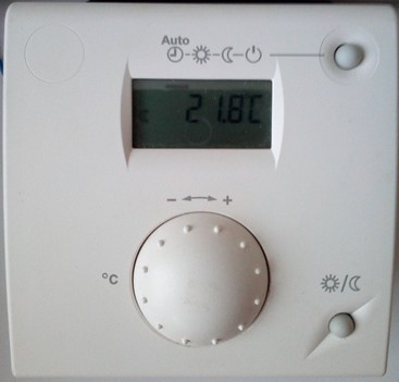
The QAA 55 room unit.
In addition to the optional measurement of the room temperature, it offers a presence button and the options for switching the operating mode and for changing the room set temperature. It only has a small LCD display that shows the current room temperature. It is connected via a two-pole cable to the BSB.
The QAA58 is the wireless version of the QAA55. It is battery operated, the AVS71.390 radio frequency receiver (868 MHz frequency) must in turn be connected to the X60 connection of the boiler controller via cable.
10.5.2 QAA75 / QAA78
The QAA75.61x is the ‘big’ ISR room unit. In addition to the integrated temperature sensor, it has the full functionality of the boiler-side control unit. In addition, there is a presence button and a manual DHW push can be triggered by pressing the DHW mode button for a longer time.
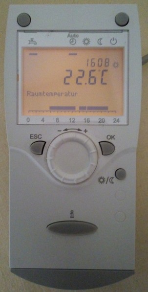
The QAA75.61x room unit.
At Broetje the QAA75.61x is called “room unit RGT”, sometimes it is also called “room unit RGT B Top”, “ISR RGT” or similar. It is also connected by cable to the BSB, with a third connection for the optional backlight available (terminal “G +” on the controller).
The QAA78.61x is the wireless version of the QAA75.61x. It is battery operated, the AVS71.390 radio frequency receiver (868 MHz frequency) must in turn be connected to the X60 connection of the boiler controller via cable. The above named “RGT” is extended by an “F” at Broetje, so it’s “RGTF”.
Note:
At this point it has to be mentioned, that obviously two different versions of the QAA75 are available: the already mentioned room unit QAA75.61x and the different looking QAA75.91x.
Whenever I’m referring to the “QAA75” in this manual, I mean the above described model QAA75.61x.
The QAA75.91x seems to offer the same functionality like the QAA75.61x, but it seems to be used only with some types of heating systems by certain manufacturers (e.g. Broetje WMS/WMC C, BMK B, BMR B and Baxi Luna Platinum+). At these types of heating systems, it seems to be used as the operating unit which is located at the housing of the heating system itself, but (in conjunction with an optional adapter, e.g. Broetje “ISR RGA”) could also be used as a room unit. In that case it seems to be still used as the operating unit, just with the additional benefit of the functions of a room unit.
A QAA75.91x operating unit, with optional equipment useable as a room unit.
10.5.3 QAA74
The QAA74 is a pretty new type of room unit at the market, which should/will replace the QAA75 in long term. At Broetje it’s called “ISR RGP” (room unit premium), at Siemens “UI400”. It is equipped with a 3,8” LCD display and a turn/push button for control purposes. Within some specific types of heating system, it’s also used as the main operating unit, named AVS74.
10.5.4 Broetje IDA
The “Broetje IDA” is a room unit which, in addition to an integrated temperature sensor and some functions, also offers a certain range of functions for controlling the heating system via app with a smartphone. A presence button is not available.
IDA is integrated into the domestic WLAN and requires Internet access, if you want to control the unit via app. In the case of purely local use of the room unit (without remote access via the app), no WLAN access is required. Incidentally, the WLAN access also updates the IDA firmware. An interesting analysis of the traffic was made here by FHEM forum member “freetz”.
For connection to the BSB of the boiler controller, a BSB interface (GTW17) must be connected. Interested user must look for “ISR IDA” in this case, so that the GTW17 is included in the package.
For controllers with the communication protocol OpenTherm (e.g. the older controller generation Broetje LMU6x), the OT interface (GTW16) must be used.
IWR-CAN-based controllers (see chapter 3.3) can directly be connected to the service dongle GW05 (WLAN gateway).
The exact functionality and installation steps of IDA are to be taken from the corresponding instructions of the manufacturer.
The parallel use of IDA and BSB-LAN is possible in principle, however, due to the report of a user (Thanks to FHEM-Foums member “mifh”!) a few restrictions regarding the functional scope of BSB-LAN are known:
If IDA is connected to the BSB, then it is the master for the settings or values of
- time and date,
- heating or switching programs and the
- room temperature.
If these settings / values are changed via BSB-LAN, they will be overwritten with the settings / values from IDA after a short time.
It is thus no longer possible, for example, to detect the room temperatures from different rooms and to transmit them to the controller via BSB-LAN, since IDA overwrites this.
The function of the presence button via BSB-LAN should still be available.
10.5.5 QAA53 / QAA73
The room units QAA 53 and QAA 73 also differ in their functional scope. They are used in the OpenTherm-based LMU6x controllers.
Further information on these room units can be found in the corresponding instructions.
10.5.6 QAA50 / QAA70
In principle, the QAA50 and QAA70 also have the same difference in functionality. These room units are used in the old controller generations, which offers only one PPS connector. When using the adapter parallel to an already existing room unit it’s only possible to read values via BSB-LAN. In that case no values and settings of the heating controller can be changed via BSB-LAN.
A QAA70 room unit.
Further information on these room units can be found in the corresponding instructions.
10.6 Special Accessories: Webserver OZW672 and Servicetool OCI700
For the sake of completeness there should two commercial solutions be mentioned, which offer access to the controller of the heating system.
Thats the webserver OZW672 and the servicetool OCI700.
The webserver OZW672 (Broetje: “ISR OZW”) is connected via bus cable to the controller and with a LAN cable to the network (and, if desired, also to the internet). If desired, one could connect with the fee-based dataportal of Broetje and offers remote access (via PC, tablet or smartphone+app) to the controller.
The OCI700 is the servicetool used by the installation engineer. It is connected to a local computer running a special software and offers an overview of the settings of the controller.
10.7 Sensor Types
| Note |
|---|
| The following list does not replace the specific description of the used plant-specific sensor types! It only serves as an illustration and is intended to show that, for example, it may also be possible to use more cost-effective, universal contact sensors as flow or return sensors! When replacing sensors or expanding the system with additional sensors, it is therefore always necessary to check the specific system documentation to see which sensors are used for the specific system! |
The current controller series use (labeled) Siemens sensors, which can be roughly divided into two different sensor types as follows:
- the outdoor temperature sensor QAC34 is a sensor of the type NTC 1k Ohm (NTC 1000 Ohm resistance at 25°C, resistance characteristic decreasing with approx. 4%/K at increasing temperature, measuring range -50…70°C, tolerance +/- 1K),
- the other sensors QAD36, QAL36, QAK36, QAR34, QAZ36 are sensors of the type NTC 10k Ohm (NTC 10k Ohm resistance at 25°C; resistance characteristic decreasing with increasing temperature).
However, these sensors differ, among other things, in their design and the measuring range of the sensor element used, even within a product category (e.g. QAD36 in the BMU or collector sensor version), so that it is not always possible to replace them with universal and more cost-effective standard sensors of the type NTC 10k Ohm (at 25°C). However, especially in the case of two or three sensor types/applications, the use of more cost-effective standard sensors of the NTC 10k Ohm (at 25°C) type is possible in principle, so these are briefly described below.
Siemens QAD36 / Broetje UAF6C
The QAD36 is a so-called “contact sensor” (Broetje: “Universal contact sensor UAF6C”) and can be used as a flow and return sensor for subsequent expansion. The sensor is housed in a casing that is mounted on the corresponding pipe (e.g. flow) and measures the temperature of the medium indirectly via the temperature of the pipe wall. As measuring element a NTC 10k Ohm (at 25°C) with a measuring range of -30…125°C, a tolerance of +/- 0,5K and a time constant of 6s is used.
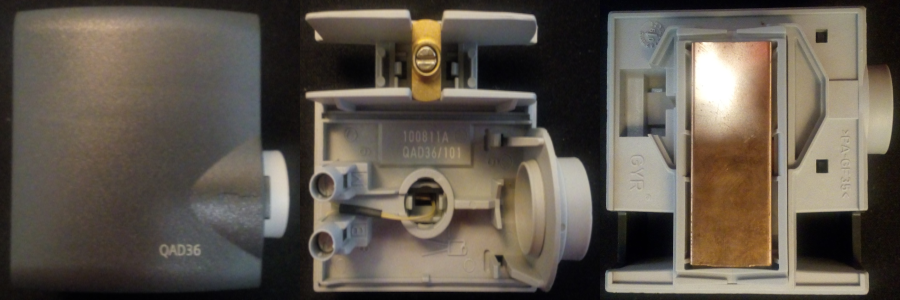
The Siemens QAD36 contact sensor, called “Universal contact sensor UAF6C” at Broetje.
As a cost-effective alternative to this sensor, a universal NTC 10k Ohm (at 25°C) pipe contact sensor can be used. These standard sensors are available in various versions, all of which have a concave bulge on one side of the metal sleeve, which makes it easier to attach the sensor to a pipe and increases the heat-transferring surface. In my opinion, the version with a brass sleeve and an additional, slightly bent brass strip is recommended here, since this version can be pushed well under a pipe insulation due to its slim design, the bending radius of the brass strip can be adapted somewhat to the pipe, and the brass conducts the heat well.
It is recommended to use a corresponding heat conductive paste for the contact surface. To prevent slipping, it is advisable to fix it with a cable tie or hose clamp.
Siemens QAZ36 / Broetje KF ISR
The QAZ36 in the solar collector sensor version (Broetje: “ISR collector sensor / KF ISR”) is an immersion sensor with an approx. 1.5m long silicone cable. The sensor element is a NTC 10k Ohm (at 25°C) with a measuring range of -30…200°C, a tolerance of +/- 0,5K and a time constant of approx. 30s. The diameter of the sleeve is 6mm, the length is 40.5mm.
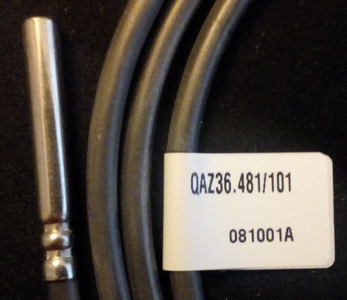
A Siemens QAZ36 collector sensor, called “ISR collector sensor / KF ISR” at Broetje.
Due to the higher ambient temperatures, it is essential to pay attention to the higher measuring range and the silicone cable when using a less expensive NTC 10k Ohm (at 25°C) standard sensor - PVC cable types are not suitable!
Siemens QAZ36 / Broetje UF6C
The QAZ36 in the version as immersion sensor with PVC cable (Broetje: “Universal immersion sensor UF6C” with 6m long PVC cable) is used e.g. for buffer or domestic hot water tanks. The sensor element is an NTC 10k Ohm (at 25°C) with a measuring range of 0…95°C, a tolerance of +/- 0,5K and a time constant of approx. 30s. The diameter of the sleeve is 6mm, the length is 40.5mm.
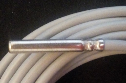
A Siemens QAZ36 immersion sensor, called “Universal immersion sensor UF6C” at Broetje.
This sensor can also be replaced by a corresponding less expensive standard sensor of the type NTC 10kOhm (at 25°C).
| Attention |
|---|
| The above-mentioned ‘immersion sensors’ are not suitable for direct immersion in liquid media! The name refers to the use in so-called ‘immersion sleeves’, such as those found in buffer or domestic hot water tanks. |
| *For older controller types, other sensor types may be used, which can be recognized by the product designation (for the outdoor temperature sensors, for example, these are “QAC21” and “QAC31”) - these sensors have other resistance values and characteristics and must not be confused with the above-mentioned sensor types! Information on the sensor types used can be found in the specific system documentation. |
