Back to TOC
Back to appendix A1
Appendix A2: Notes on the Circuit Diagram
Note: The circuit diagram for the ESP32 version is basically the same like the one for the Due, just the EEPROM isn’t needed.
A2.1 Short Explanation of the Circuit Diagram
D1 = LED (red)
D2 = Diode
EEPROM = EEPROM
OK(x) = Optocouplers
Q(x) = Transistor
R(x) = Resistor
ARD = Arduino
RPI = Raspberry Pi
CL+/- = BSB connectors
DB/MB = LPB connectors
TXD = Digital pin: transmit
RXD = Digital pin: receive
A2.2 Parts List
| Amount | Component | Label | Illustration | Note |
|---|---|---|---|---|
| 1 | LED (red) | D1 |  |
operating voltage max. 2,8V, reverse voltage 5V Observe alignment! |
| 1 | Diode 1N4148 | D2 |  |
Observe alignment! |
| 1 | EEPROM 24LC32A-I/P | EEPROM |  |
not needed for the ESP32 version of the PCB Observe alignment! |
| 2 | Optocoupler 4N25 | OK1, OK2 |  |
Observe alignment! |
| 1 | Transistor BC547 | Q1 |  |
Attention: do not confuse with Q2! Observe alignment! |
| 1 | Transistor BC557 | Q2 |  |
Attention: do not confuse with Q1! Observe alignment! |
| 3 | Resistor 330kΩ | R1, R4, R7 |  |
orange, orange, black, orange, brown |
| 1 | Resistor 1.5kΩ | R2 |  |
brown, green, black, brown, brown |
| 1 | Resistor 300Ω | R3 |  |
orange, orange, black, black, brown |
| 2 | Resistor 4.7kΩ | R5, R6 |  |
yellow, violet, black, brown, brown |
| 1 | Connector | CL+/CL |  |
grid dimension 5,08mm |
Arduino Due:
Pin header (male, grid dimension 2,54mm), optional IC sockets for optocouplers and/or EEPROM..
For the usage of the adapter v4 in conjunction with an Arduino Due you basically only need to assemble the pins for RX1, TX1, SDA, SCL, GND and pin 53. Other pins could be assembled due to a better stability and/or other usage.
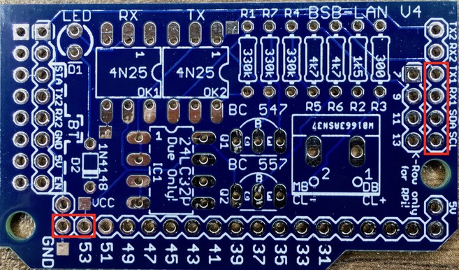
Absolutely necessary pins for the usage in conjunction with an Arduino Due.
Raspberry Pi:
Female pinheader (double row, grid dimension 2,54mm), optional IC sockets for optocouplers and/or EEPROM..
For the usage of the adapter v4 in conjunction with a Raspberry Pi you have to put your attention on different things, which are collectively named within the chapter 12.9.
ESP32:
Female pinheader (grid dimension 2,54mm; ESP32: single row; Olimex: double row 2x5), optional IC sockets for optocouplers..
For the use of the ESP32 specific adapter v4 on the recommended ESP32 NodeMCU from Joy-It only the pins RX2, TX2, GND and 3.3V are needed and must be equipped with corresponding pin headers. However, for stability reasons it is recommended to equip both sides completely with one row of pin headers each.
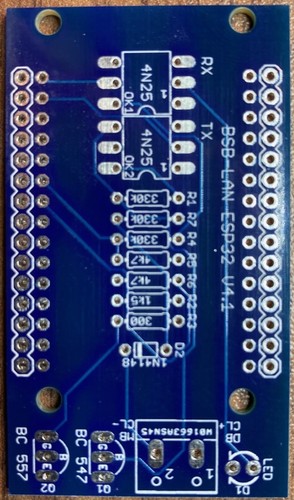
The unpopulated ESP32 specific adapter board.
A2.3 General Notes
Important: Before soldering, study the circuit diagram attentively!
The following instructions do not replace any fundamental electronic knowledge, but maybe one or two of these hints could be helpful for electronics beginners.
Generally it is helpful to position the components, bend the ‘legs’ of them a little bit to hold them in position on the board and check again the positioning of each component. Start with the smallest parts first. Pay attention to the correct alignment of parts like diodes, transistors and ICs! If everything seems fine, you can turn around the board and start soldering. Be careful that you just solder where you should so that you don’t produce shortcuts by accident.
A previous breadboard test setup (if you don’t use the PCB) of course could be an option, though
due to non-exclude problem sources (usage of a wrong
plug row, possible loose contacts and so on) not necessarily
recommended.
Please make sure that the components do not get too hot during soldering, since they can be damaged. Therefore it is appropriate to use corresponding IC sockets for the optocoupler ICs and the EEPROM. Once you are done with the soldering, you can just plug in the ICs. Pay attention to the correct alignment of the sockets and optocouplers/EEPROM as well as of the diodes and transistors!
Before putting the adapter into operation, it is advisable to thoroughly check the assembly again and (if possible) measure the circuit with a multimeter. Cold solder joints, accidentally bridged contacts and so on can cause inexplicable and difficult to diagnose misconduct of the adapater up to an eventual controller defect!
Good luck!
